
2 layers149 × 65 mm

birb
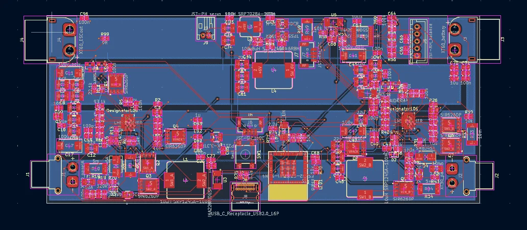
Solar is an open-source printed circuit board by DinosaurPotato534, from the DinosaurPotato534/Project-Albatross repository on GitHub. It is a 2-layer board of 149.6 × 65 mm with 201 parts on 137 nets, routed with 1,379 tracks and 197 vias.
It is built around the ESP32-C3-MINI-1-N4, LM5175RHFR and TPS54202DDCR, with the AP2112K-3.3TRG1, BAT54 and SMBJ45A among its other parts. Its parts include 86 capacitors, 69 resistors, 13 ICs, 12 transistors and 9 connectors. It belongs with the power boards and the ESP32 and RISC-V boards of this library.


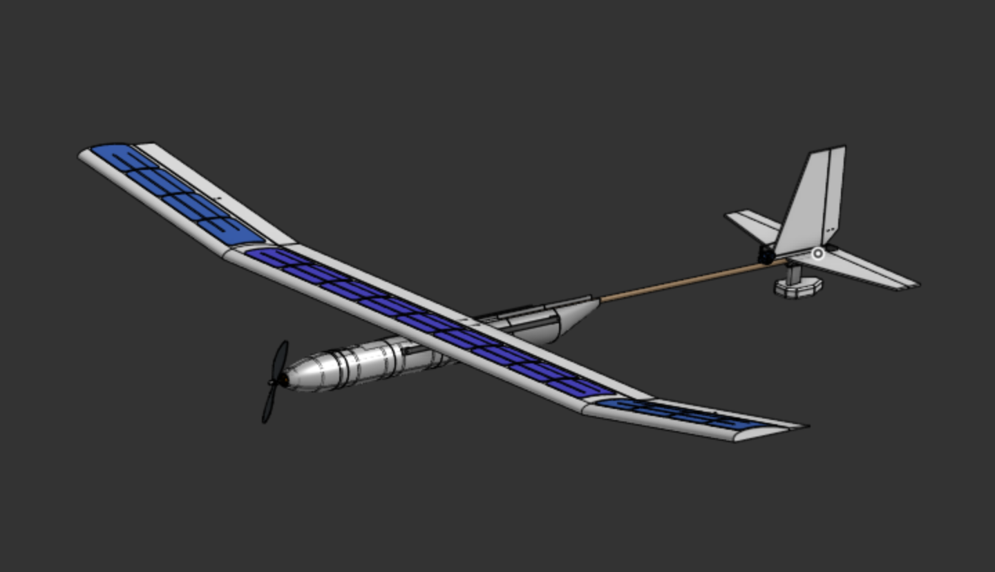
The goal for the project was to create an autonomous plane capable of flying for hours off of solar power. Another big aspect is the ability to takeoff from water using a pontoon system mounted to a 4-bar linkage. The plane is going to be made from foam board and 3d prints. The wingspan is 90in and the length is roughly 6ft.
We wanted to explore the idea of multi-hour flight using solar power. Most rc planes have a relatively short flight time, but we wanted to try and expand on that. That is why we also added the pontoons, so it could recharge on the surface of water.
The pontoon mechanism works by having two hollow 3D printed hulls swing out when landing. The reason we decided to put them on a swinging mechanism was that it would greatly reduce drag, and in turn air resistance. Just based on frontal area that's around a 25% increase in efficiency. They will be driven by a motor that will winch it up or down.
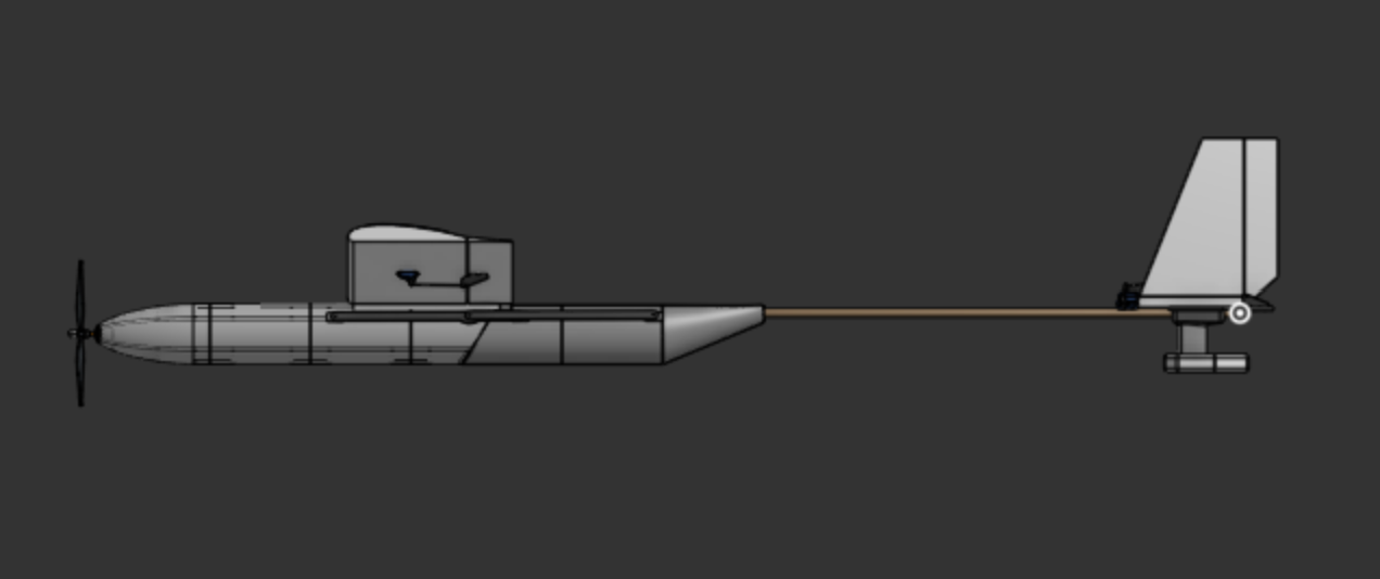
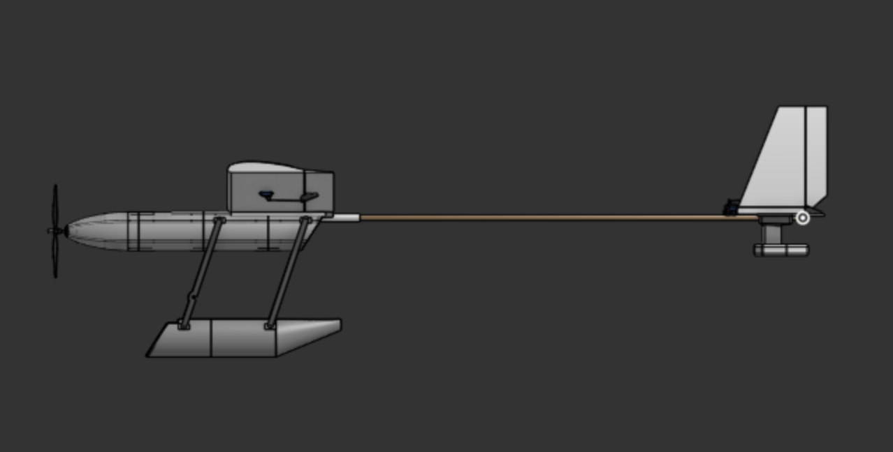
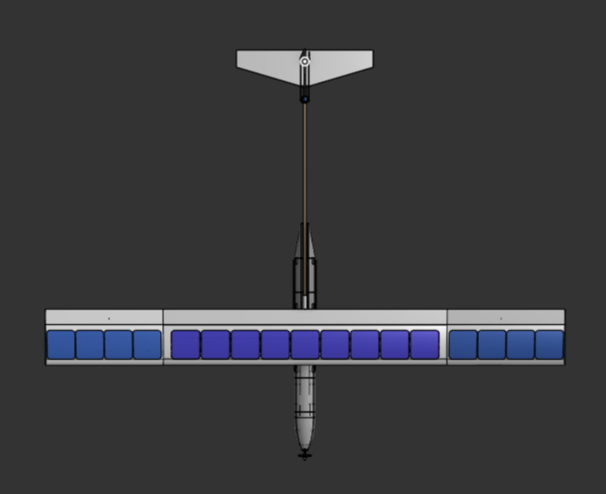
The solar panels just sit on the wing and will be wired to an MPPT board. They each generate around 3.5W in full sun, and there will be 17. It should be enough to sustain flight, but it will almost never get perfect lighting, so we will see. These sit on a 90in wing that has an 7in chord (not including the ailerons). Panels measure 125mm, so roughly 5in.
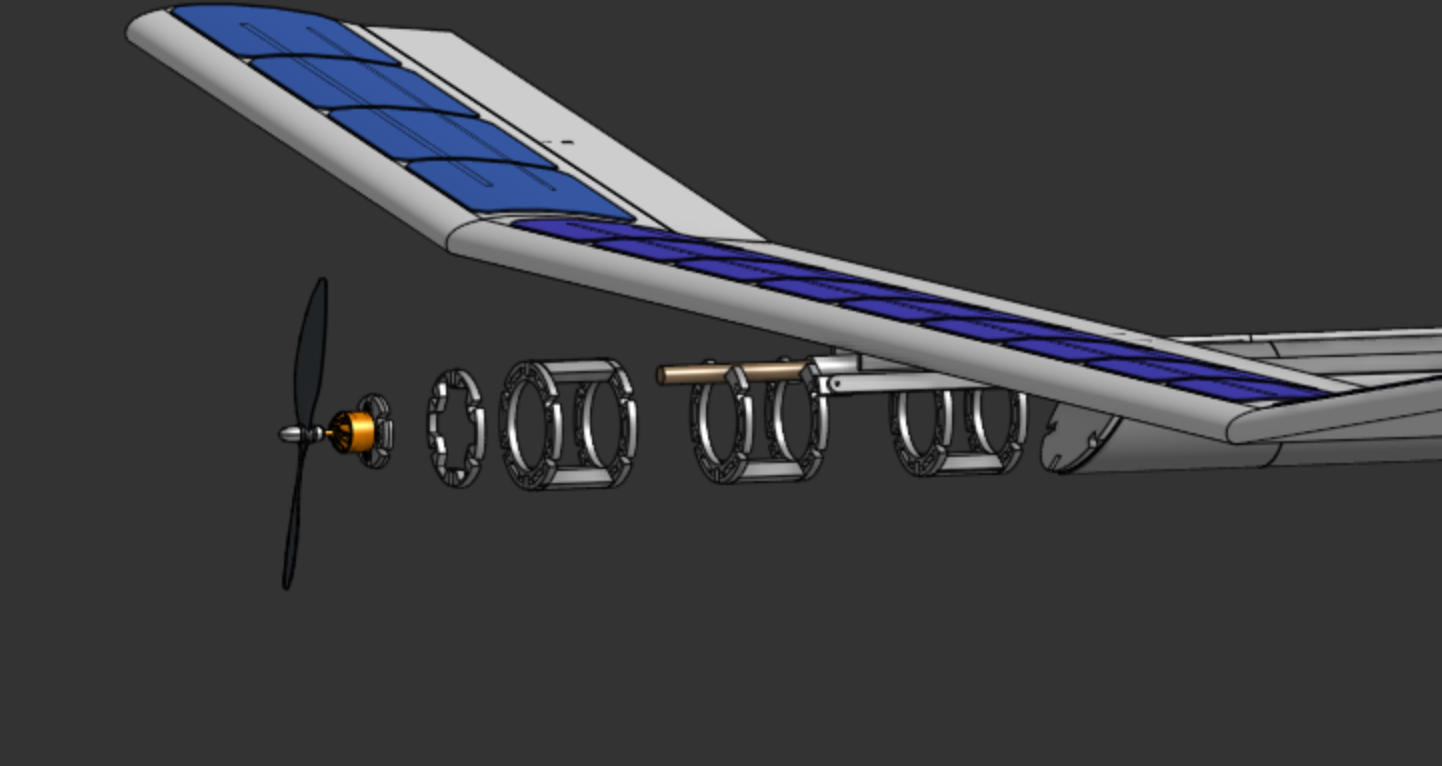
Used a series of ribs inside to support a really thin outer shell of 3D print. These will slide down into their corresponding spots, making the structure much stronger. The front one also serves as the motor mount too.
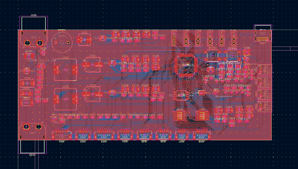
The flight controller was built with Ardupilot in mind, with multiple connectors allowing for different sensors to be modular and swapped out. It is designed to take a 3 or 4S battery, and runs on an STM32F405RGT6. We are planning on using a GPS and a magnetometer but we have extra connector for different sensors if we want to add them going forward. We also have an IMU and pressure sensor on the board.
We made a full solar circuit, with a MPPT board and BMI. With this plane design we kept the wings relatively small. Only 17 solar panels could fit. With each solar panel proving roughly 0.6V the total voltage was roughly 10V. This is well below the standard voltage of a 4s battery, thus we needed a step up MPPT board. The market for this is miniscule and expensive leading our design to be useful as it functioned as both a step up and step down board depending on the solar array. However, our board also ended up being far to expensive to become justifiable. We decided to pivot to using a standard step down MPPT and increasing the solar area, as well as deceasing the battery voltage to a 3S.
Most of the planes assembly consists of techniques similar to other rc planes. The wings are made from foam board "wrapped" around a dowel spar. They are made by cutting 3 slits across a sheet of foam board spaced out at 7in, 8iin, and 17 from one end. Then the paper layer of the foam board is peeled off for the top of the airfoil to create a better curve. The foam board is folded over the wing spar and three sections of these are connected.
The body is made from a dowel as the main structure of the hull, with 3d printed shells for aerodynamics and part containers. The slide onto the dowel and will be hot glued into place. Then the electronics are wired and placed into the nose cone of the 3d printed hull. The pontoons can then be mounted on they're hinges, which will be connected to n20 motor to swing up and down. Solar panels will be mounted on the wing using a plastic wrap to hold them in place, while still allowing sunlight through.
Both the pcbs, especially the mppt board, are rather complex and have a lot of smd soldering. The use of a hot plate will be need and following the design the components will be soldered on. These boards will then be wired and hooked up to the rest of the planes electronics.
| Description | Quantity | Price | Link |
|---|---|---|---|
| Main Brushless Motor | 0 | 19.98 | View |
| Propeller | 0 | 9.19 | View |
| Light Weight PLA | 1 | 29.99 | View |
| Solar Panels | 30 | 4 | View |
| Servos (5 Pack) | 1 | 15.99 | View |
| Servo Extention Cables | 1 | 9.99 | View |
| 3S Lipo | 0 | 16.99 | View |
| ESC | 0 | 28.4 | View |
| Heat Set Inserts | 1 | 4.99 | View |
| M3 Screws | 1 | 6.99 | View |
| Controller | 0 | 54.89 | View |
| Foam Board | 10 | 1.25 | View |
| N20 Motor | 4 | 4.17 | View |
| GPS | 1 | 15.9 | View |
| Telemetry | 1 | 65.9 | View |
| BMS | 1 | 1.13 | View |
| MPPT Board | 1 | 20.41 | View |
| passive piezo | 5 | 0.4017 | View |
| 100u/35V poly | 50 | 0.0139 | View |
| 100n/50V 0603 | 10 | 0.2003 | View |
| 10u/25V 1210 | 10 | 0.2257 | View |
| 22u/16V 1210 | 20 | 0.0291 | View |
| 1u 0805 | 100 | 0.005 | View |
| 100n 0402 | 10 | 0.0614 | View |
| 4.7u 0805 | 50 | 0.0138 | View |
| 1u 0603 | 50 | 0.0191 | View |
| 2.2u 0603 | 100 | 0.007 | View |
| 10p 0402 | 10 | 0.0803 | View |
| 470u/16V 8x10.5 | 5 | 0.2003 | View |
| 10u 1210 | 5 | 0.1813 | View |
| 10u/16V 1210 | 20 | 0.04 | View |
| 2.2u/6.3V 0603 | 10 | 0.061 | View |
| 10n/16V 0603 | 4 | 0.5 | View |
| SMBJ20A | 5 | 0.16 | View |
| BAT54C | 1 | 2.7641 | View |
| Fuse 3A 1206 | 10 | 0.0283 | View |
| 600R@100MHz 0805 | 3 | 0.65 | View |
| USB4085 | 1 | 0.91 | View |
| Connector_PinHeader_1.27mm:PinHeader_1x06_P1.27mm_Vertical | 5 | 0.2606 | View |
| Connector_PinHeader_2.54mm:PinHeader_1x03_P2.54mm_Vertical | 20 | 0.0278 | View |
| Connector_JST:JST_PH_S2B-PH-K_1x02_P2.00mm_Horizontal | 10 | 0.0669 | View |
| Connector_JST:JST_GH_BM06B-GHS-TBT_1x06-1MP_P1.25mm_Vertical | 5 | 0.3036 | View |
| Connector_JST:JST_GH_BM04B-GHS-TBT_1x04-1MP_P1.25mm_Vertical | 10 | 0.1301 | View |
| Connector_JST:JST_GH_BM03B-GHS-TBT_1x03-1MP_P1.25mm_Vertical | 5 | 0.2223 | View |
| Connector_JST:JST_GH_BM05B-GHS-TBT_1x05-1MP_P1.25mm_Vertical | 1 | 0.5359 | View |
| 10uH SRP7028A-100M | 1 | 1.1 | View |
| 6.8uH SRP1245A-6R8M | 2 | 1.47 | View |
| red LED_0603 | 2 | 0.14 | View |
| blue LED_0603 | 2 | 0.16 | View |
| green PWR LED_0603 | 2 | 0.14 | View |
| 2N7002 | 50 | 0.0112 | View |
| 1m 2512 | 20 | 0.0512 | View |
| 63.4k 0603 | 10 | 0.021 | View |
| 10k 0603 | 25 | 0.024 | View |
| 75k 0603 | 10 | 0.028 | View |
| 90.9k 0603 | 10 | 0.021 | View |
| 47k 1% 0603 | 10 | 0.025 | View |
| 10k 1% 0603 | 10 | 0.032 | View |
| 5.1k 0402 | 10 | 0.021 | View |
| 4.7k 0603 | 10 | 0.025 | View |
| 10k 0402 | 10 | 0.02 | View |
| 100k 0603 | 10 | 0.025 | View |
| 0R15 0.5W 1206 | 10 | 0.299 | View |
| 330R 0603 | 10 | 0.025 | View |
| 220R 0603 | 10 | 0.025 | View |
| 470R 0603 | 10 | 0.02 | View |
| 1k 0603 | 10 | 0.025 | View |
| B3S-1000 | 5 | 0.34 | View |
| INA228AIDGSR | 1 | 4.68 | View |
| TPS54202DDCR | 1 | 1.53 | View |
| TPS54302DDCR | 2 | 1.41 | View |
| AP2112K-3.3TRG1 | 2 | 0.28 | View |
| STM32F405RGT6 | 1 | 6.47 | View |
| USBLC6-2SC6 | 2 | 0.54 | View |
| ICM-42688-P | 1 | 4.91 | View |
| C50506 | 1 | 2.4967 | View |
| W25Q128JVSIQ | 1 | 2.62 | View |
| DRV8833PWP | 2 | 2.5 | View |
| 8.000MHz 10ppm CL8pF | 2 | 0.73 | View |
| PCB | 1 | 8.4 | View |
| Shipping | |||
| Amazon | 1 | 0 | |
| JLCPCB | 1 | 8.4132 | |
| Aliexpress | 1 | 0 | |
| Digikey | 1 | 16.67 | |
| LCSC | 1 | 11.81 | |
| Ebay(Tax) | 1 | 7.66 | |
| RoboFusion | 1 | 5.9 | |
| Total | 458.7009 |
| Qty | Value | Footprint | References |
|---|---|---|---|
| 36 | 100n | Capacitor_SMD:C_0603_1608Metric | C1, C2, C4, C10, C16, C21, C23, C24, C25, C27, C31, C32, C34, C40, C46, C51 +20 |
| 23 | 10k | Resistor_SMD:R_0603_1608Metric | R5, R6, R12, R14, R16, R20, R29, R30, R31, R32, R36, R38, R40, R44, R57, R60 +7 |
| 21 | 22u | Capacitor_SMD:C_1210_3225Metric | C6, C7, C12, C13, C14, C15, C36, C37, C38, C39, C42, C43, C44, C45, C74, C75 +5 |
| 8 | 2.2 | Resistor_SMD:R_0603_1608Metric | R1, R2, R3, R4, R25, R26, R27, R28 |
| 8 | SIR626DP | Package_SO:PowerPAK_SO-8_Single | Q1, Q2, Q3, Q4, Q5, Q6, Q7, Q8 |
| 7 | 100 | Resistor_SMD:R_0603_1608Metric | R50, R51, R52, R53, R54, R55, R56 |
| 5 | 1u | Capacitor_SMD:C_0805_2012Metric | C5, C28, C35, C58, C68 |
| 4 | 100u_poly | Capacitor_Tantalum_SMD:CP_EIA-7343-31_Kemet-D | C11, C17, C41, C47 |
| 4 | 10u | Capacitor_SMD:C_0603_1608Metric | C70, C71, C77, C78 |
| 4 | Q_NMOS_GSD | 2N7002:TRANS_2N7002 | Q9, Q10, Q11, Q12 |
| 3 | 10u | Capacitor_SMD:C_0805_2012Metric | C3, C33, C86 |
| 3 | 1u | Capacitor_SMD:C_0603_1608Metric | C85, C88, C93 |
| 3 | INA228AIDGSR | INA228AIDGSR:SOP50P490X110-10N | U3, U4, U5 |
| 2 | 100p | Capacitor_SMD:C_0603_1608Metric | C20, C50 |
| 2 | 10A | Fuse:Fuse_1206_3216Metric | F1, F2 |
| 2 | 10m | Resistor_SMD:R_2512_6332Metric | R9, R33 |
| 2 | 10uH SRP1245A-100M | Inductor_SMD:L_Bourns_SRP1245A | L1, L2 |
| 2 | 120k | Resistor_SMD:R_0603_1608Metric | R19, R43 |
| 2 | 130k | Resistor_SMD:R_0603_1608Metric | R13, R37 |
| 2 | 1M | Resistor_SMD:R_0603_1608Metric | R21, R45 |
| 2 | 2.2k | Resistor_SMD:R_0603_1608Metric | R73, R74 |
| 2 | 22.1k | Resistor_SMD:R_0603_1608Metric | R11, R35 |
| 2 | 22n | Capacitor_SMD:C_0603_1608Metric | C26, C56 |
| 2 | 22p | Capacitor_SMD:C_0603_1608Metric | C18, C48 |
| 2 | 33k | Resistor_SMD:R_0603_1608Metric | R15, R39 |
| 2 | 390p | Capacitor_SMD:C_0603_1608Metric | C22, C52 |
| 2 | 4.7k | Resistor_SMD:R_0603_1608Metric | R22, R46 |
| 2 | 4.7n | Capacitor_SMD:C_0603_1608Metric | C19, C49 |
| 2 | 5.1k | Resistor_SMD:R_0603_1608Metric | R75, R76 |
| 2 | 5m | Resistor_SMD:R_2512_6332Metric | R10, R34 |
| 2 | 84.5k | Resistor_SMD:R_0603_1608Metric | R17, R41 |
| 2 | 93.1k | Resistor_SMD:R_0603_1608Metric | R18, R42 |
| 2 | BAT54 | Diode_SMD:D_SOD-323 | D2, D3 |
| 2 | LM5175RHFR | LM5175RHFR:RHF0028A | U1, U2 |
| 2 | SMBJ45A | Diode_SMD:D_SMB | D1, D4 |
| 2 | TLV9061IDCKR | TLV9061IDCKR:DCK5_TEX | U7, U8 |
| 1 | 0R | Resistor_SMD:R_0603_1608Metric | R99 |
| 1 | 100k | Resistor_SMD:R_0603_1608Metric | R59 |
| 1 | 10k_NTC | Resistor_SMD:R_0603_1608Metric | R58 |
| 1 | 10uH SRP7028A-100M | Inductor_SMD:L_Bourns_SRP7028A_7.3x6.6mm | L3 |
| 1 | 1k | Resistor_SMD:R_0603_1608Metric | R72 |
| 1 | 1m | Resistor_SMD:R_2512_6332Metric | R49 |
| 1 | 6.8uH SRP1245A-6R8M | Inductor_SMD:L_Bourns_SRP1245A | L4 |
| 1 | 75k | Resistor_SMD:R_0603_1608Metric | R64 |
| 1 | 90.9k | Resistor_SMD:R_0603_1608Metric | R68 |
| 1 | AP2112K-3.3TRG1 | AP2112K_3_3TRG1:SOT_RG1_DIO | U11 |
| 1 | BQ7692000PWR | BQ7692000PWR:PW0020A_N | U6 |
| 1 | ESP32-C3-MINI-1-N4 | ESP32_C3_MINI_1_N4:ESP32-C3-MINI-1_EXP | U12 |
| 1 | JST-GH_I2C | Connector_JST:JST_GH_BM04B-GHS-TBT_1x04-1MP_P1.25mm_Vertical | J7 |
| 1 | JST-GH_toFC | Connector_JST:JST_GH_BM04B-GHS-TBT_1x04-1MP_P1.25mm_Vertical | J6 |
| 1 | JST-PH_servo | Connector_JST:JST_PH_S2B-PH-K_1x02_P2.00mm_Horizontal | J9 |
| 1 | JST-XH_balance | Connector_JST:JST_XH_B5B-XH-A_1x05_P2.50mm_Vertical | J5 |
| 1 | MCP4728A0T-E_UN | MCP4728A0T_E_UN:MSOP10_MC_MCH | U13 |
| 1 | TPS54202DDCR | TPS54202DDCR:DDC0006A_N | U9 |
| 1 | TPS54302DDCR | TPS54202DDCR:DDC0006A_N | U10 |
| 1 | USB_C_Receptacle_USB2.0_16P | Connector_USB:USB_C_Receptacle_GCT_USB4085 | J8 |
| 1 | XT30_panelA | Connector_AMASS:AMASS_XT30PW-F_1x02_P2.50mm_Horizontal | J1 |
| 1 | XT30_panelB | Connector_AMASS:AMASS_XT30PW-F_1x02_P2.50mm_Horizontal | J2 |
| 1 | XT60_ESCout | Connector_AMASS:AMASS_XT60PW-F_1x02_P7.20mm_Horizontal | J4 |
| 1 | XT60_battery | Connector_AMASS:AMASS_XT60PW-F_1x02_P7.20mm_Horizontal | J3 |
| 1 | green | LED_SMD:LED_0603_1608Metric | LED1 |
| 1 | tact | Button_Switch_SMD:SW_SPST_B3S-1000 | SW1 |

OpenModbus/OM-64DO
A compact industrial-grade 64-channel Modbus RTU output module.

anshchawla521/DIY_T12_iron
This repository conatins all the files for the DIY soldering iron which is compatible with hakko 936 style station and is meant to be used as the replacement PCB for HAKKO 936 style clones.

aryanthomare/SmartKnob
A programmable force-feedback knob for your computer. Custom motor-driver PCB, closed-loop haptic firmware, a native Windows companion app and a parametric 3D-printed enclosure, all designed in house.

RotemCarr/snowboard-fc
Snowboard flight controller hardware and software stacks - using the Zephyr framework


atomicra1n/wifi-geiger-counter
A DIY Geiger counter PCB which can detect ionizing radiation and log readings over Wi-Fi. Built with an ESP32, and a HV multiplier circuit that steps up 3.7V to 400V for the GM tube.

iancho-eng/Smart-Tactile-Controller
A five-key USB-C macro pad built around an ESP32-C3 — from KiCad schematic to fabricated PCB and 3D-printed enclosure.

noellayang/chipsat-v1
Custom ESP32-C3 power-management testbed for small satellite firmware experiments
It measures 149.6 × 65 mm and has 2 copper layers, 1.6 mm thick.
201 parts, built around the ESP32-C3-MINI-1-N4, LM5175RHFR, TPS54202DDCR and AP2112K-3.3TRG1. The full list of its parts is on this page, with links to each part's symbol and footprint where PCBKit's library has them.
From the DinosaurPotato534/Project-Albatross repository on GitHub, at the commit this page was made from: the board is pcb/solar-board/solar.kicad_pcb and its schematic pcb/flight-controller/01_power.kicad_sch. PCBKit opens the board in the browser, with nothing to install.
Its repository states no licence, so its author keeps all rights: ask DinosaurPotato534 before reusing the design.