2 layers
AD Wandler Validation Board
DerZaske/adc_validation_platform
A precision ADC validation platform for characterizing anlog front-end performance, signal integrity, and coversion accuracy.
50 partsMIT
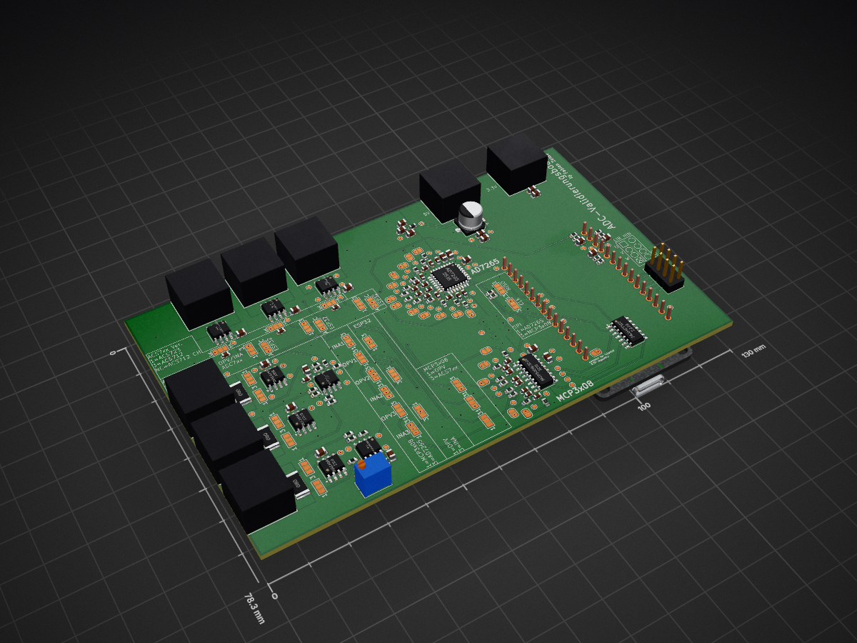
 DerZaske/adc_validation_platform
A precision ADC validation platform for characterizing anlog front-end performance, signal integrity, and coversion accuracy.
AD Wandler Validation Board is an open-source printed circuit board by DerZaske, from the DerZaske/adc_validation_platform repository on GitHub, published under the MIT licence. It is a 4-layer board of 130 × 78.3 mm with 246 parts on 157 nets, routed with 847 tracks and 241 vias.
It is built around the 74AHCT125D, INA240A1D and AD7265BCP. Its parts include 51 capacitors, 46 resistors, 12 ICs and 9 connectors.


A modular testbed for evaluating analog signal chains in motor control applications
Work in Progress: This repository is actively developed as part of my Master’s project at HTWG Konstanz. The current README is a draft and will be expanded with hardware designs, firmware, and validation results.
This repository provides design files, firmware, and validation tools for a custom ADC validation board, developed as an extension to my Bachelor’s thesis the "DIY Power PCB" (HTWG Konstanz, 2025). While the original thesis used the ESP32’s internal ADC (limited by nonlinearity and noise), this platform focuses on:
External ADC Validation:
Full Analog Chain Analysis:
BLDC Motor Control Context:
adc-validation-board/
├── hardware/          # KiCad schematics, PCB layouts, BOM
├── firmware/          # Source code for MCU
├── software/          # Test scripts (Python/MATLAB)
├── docs/              # Datasheets, thesis excerpts, results
└── images/ # Photos, plots, diagrams git clone https://github.com/your-username/adc-validation-board.git cd software/tests
python3 noise_analysis.pyKey findings from the thesis:
Example: Noise spectrum of the ADC at 1 kSPS
🔗 Full results in the thesis [blocked]
[2–3 sentences summarizing your thesis goals, e.g.:
"This work evaluates the suitability of the [ADC Model] for precision applications in embedded systems. A custom validation board was designed to measure noise, linearity, and temperature effects, achieving [key result] under [conditions].")
📄 Download the full thesis (PDF)
Contributions are welcome! Open an issue or submit a pull request for:
This project is licensed under the MIT License – see LICENSE for details.
Fabian Zaske – your.email@example.com
🔗 Portfolio/Website | LinkedIn
"Precision matters – in bits and in life."
| Qty | Value | Footprint | References |
|---|---|---|---|
| 77 | TestPoint | TestPoint:TestPoint_Pad_D1.0mm | TP1, TP2, TP10, TP11, TP12, TP13, TP14, TP15, TP16, TP17, TP18, TP19, TP20, TP21, TP22, TP23 +61 |
| 29 | SolderJumper_3_Open | Jumper:SolderJumper-3_P1.3mm_Open_Pad1.0x1.5mm_NumberLabels | JP1, JP2, JP10, JP11, JP12, JP13, JP14, JP15, JP16, JP17, JP18, JP21, JP22, JP23, JP24, JP25 +13 |
| 14 | 0.1µF | Capacitor_SMD:C_0805_2012Metric | C3, C5, C9, C10, C11, C12, C13, C14, C19, C20, C45, C47, C49, C50 |
| 13 | 1nF | Capacitor_SMD:C_0603_1608Metric | C6, C7, C8, C16, C17, C31, C32, C33, C34, C35, C36, C37, C38 |
| 12 | 100R | Resistor_SMD:R_0603_1608Metric | R25, R26, R27, R28, R29, R30, R37, R38, R39, R40, R41, R42 |
| 12 | 10nF | Capacitor_SMD:C_0603_1608Metric | C25, C26, C27, C28, C29, C30, C39, C40, C41, C42, C43, C44 |
| 12 | NetTie_2 | Jumper:SolderJumper-2_P1.3mm_Open_RoundedPad1.0x1.5mm | NT7, NT8, NT9, NT10, NT11, NT12, NT13, NT14, NT15, NT16, NT17, NT18 |
| 8 | 47R | Resistor_SMD:R_0603_1608Metric | R31, R32, R33, R34, R35, R36, R43, R44 |
| 8 | ~ | ADC_Validation_Board:691313510002 | J1, J2, J3, J4, J5, J6, J7, J8 |
| 6 | 1k 0.1% | Resistor_SMD:R_0603_1608Metric | R7, R8, R9, R13, R14, R15 |
| 6 | 20k 0.1% | Resistor_SMD:R_0603_1608Metric | R10, R11, R12, R16, R17, R18 |
| 6 | SolderJumper_2_Open | Jumper:SolderJumper-2_P1.3mm_Open_RoundedPad1.0x1.5mm | JP19, JP20, JP30, JP31, JP32, JP35 |
| 3 | 100nF | Capacitor_SMD:C_0805_2012Metric | C22, C23, C24 |
| 3 | 10K | Resistor_SMD:R_0603_1608Metric | R22, R23, R24 |
| 3 | 10m | Resistor_SMD:R_2512_6332Metric | R4, R5, R6 |
| 3 | 10µF | Capacitor_SMD:C_0805_2012Metric | C1, C4, C15 |
| 3 | 1µF | Capacitor_SMD:C_0805_2012Metric | C18, C21, C48 |
| 3 | 2K | Resistor_SMD:R_0603_1608Metric | R19, R20, R21 |
| 3 | ACS712_20A/ACS723_20A | Package_SO:SOIC-8_3.9x4.9mm_P1.27mm | U1, U2, U3 |
| 3 | INA240A1D | Package_SO:SOIC-8_3.9x4.9mm_P1.27mm | U5, U6, U7 |
| 3 | NetTie_2 | NetTie:NetTie-2_SMD_Pad2.0mm | NT1, NT2, NT3 |
| 2 | 10k | Resistor_SMD:R_0603_1608Metric | R2, R3 |
| 2 | 470nF | Capacitor_SMD:C_0603_1608Metric | C46, C51 |
| 2 | MCP6002/TLV9062/OPA314-8pin-SOIC | Package_SO:SOIC-8_3.9x4.9mm_P1.27mm | U4, U8 |
| 1 | 1.2k | Resistor_SMD:R_0603_1608Metric | R46 |
| 1 | 120uF | Capacitor_SMD:CP_Elec_6.3x5.9 | C2 |
| 1 | 680R | Resistor_SMD:R_0603_1608Metric | R45 |
| 1 | 74AHCT125 | Package_SO:SO-14_3.9x8.65mm_P1.27mm | U10 |
| 1 | AD7265 | Package_QFP:TQFP-32_7x7mm_P0.8mm | U11 |
| 1 | Conn_02x04_Odd_Even | Connector_PinHeader_2.54mm:PinHeader_2x04_P2.54mm_Vertical | J9 |
| 1 | ESP WROOM-32 CH340C Exinko | ADC_Validation_Board:ESP-32 DIP30 | U12 |
| 1 | FerriteBead 600R@100MHz | Inductor_SMD:L_0603_1608Metric | FB1 |
| 1 | MCP3008/3208 | Package_SO:SOIC-16_3.9x9.9mm_P1.27mm | U9 |
| 1 | R_Trim | Potentiometer_THT:Potentiometer_Bourns_3266Y_Vertical | R1 |
DerZaske/adc_validation_platform
A precision ADC validation platform for characterizing anlog front-end performance, signal integrity, and coversion accuracy.


sequoia-hope/rp2350-motor-controller
An RP2350 based brushless motor controller


RoMeLaUCLA/romela-motor-driver
Motor driver PCB and firmware designed for RoMeLa actuators.


G-Pereira/greenmobi-drive
A FOC motor drive compatible with VESC

aguscsc/Model-Predictive-Control-Strategies-for-Fourth-Order-Power-Converters
This repository contains the design an implementation of a SEPIC (Single-Ended Primary-Inductor Converter) to test and compare the application of model predictive control on fourth-order power converters.

ajisrawi/sentinel-uhf-radar
Reference design of a two-face UHF early-warning phased-array radar: system sizing, MoM antenna simulation, seven KiCad PCB projects, Blender site model
It measures 130 × 78.3 mm and has 4 copper layers, 1.6 mm thick.
246 parts, built around the 74AHCT125D, INA240A1D and AD7265BCP. The full list of its parts is on this page, with links to each part's symbol and footprint where PCBKit's library has them.
From the DerZaske/adc_validation_platform repository on GitHub, at the commit this page was made from: the board is Hardware/AD-Wandler-Validation-Board/AD-Wandler-Validation-Board.kicad_pcb and its schematic Hardware/AD-Wandler-Validation-Board/AD-Wandler-Validation-Board.kicad_sch. PCBKit opens the board in the browser, with nothing to install.
Its repository publishes it under the MIT licence: you may reuse it on that licence's terms (keep the author's notice, and for a copyleft licence share your changes alike).