2 layers103 × 30.5 mm
 DaveCalaway/PWMtoPWM
That board change the a pwm_in pulse in to other pwm_out pulse. Oled display integration.
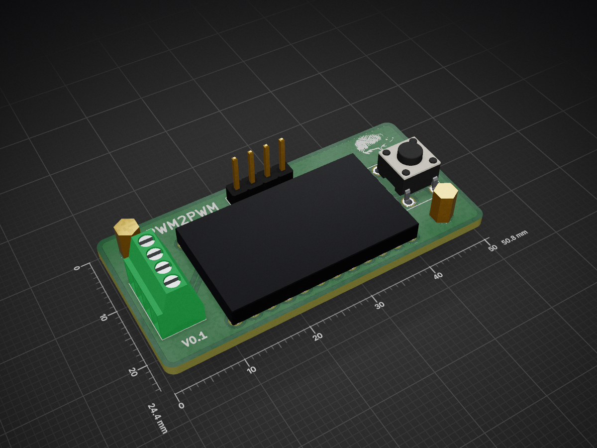
PWMtoPWM is an open-source printed circuit board by DaveCalaway, from the DaveCalaway/PWMtoPWM repository on GitHub, published under the MIT licence. It is a 2-layer board of 50.8 × 24.4 mm with 9 parts on 23 nets, routed with 35 tracks and 0 vias.
Its parts include 2 resistors, 2 connectors and 1 switch. It belongs with the lEDs and displays boards of this library.
In that repo we have 2 project:
Dave Calaway.
| Qty | Value | Footprint | References |
|---|---|---|---|
| 2 | 10k | Resistors_THT:R_Axial_DIN0207_L6.3mm_D2.5mm_P10.16mm_Horizontal | R1, R2 |
| 1 | ARDUPROMINI-6 | ArduProMiniTKB:ArduProMini-6 | uP1 |
| 1 | Conn_01x04 | Pin_Headers:Pin_Header_Straight_1x04_Pitch2.54mm | J1 |
| 1 | LOGO | logos:hedgehog_9000 | G*** |
| 1 | Rotary_Encoder_Switch | Buttons_Switches_THT:KSA_Tactile_SPST | SW1 |
| 1 | Screw_Terminal_01x04 | TerminalBlocks_Phoenix:TerminalBlock_Phoenix_MPT-2.54mm_4pol | J2 |
The 7 most common of 9 parts.


FrameworkComputer/ExpansionCards
Reference designs and documentation to create Expansion Cards for the Framework Laptop

VoronDesign/Voron-Hardware
Cool Hardware designed by the Voron Design group

hackclub/OnBoard
💡 Join 1,000 teenagers and make your first PCB with a $100 grant!


adamws/kicad-kbplacer
KiCad plugin for automatic keyboard's key placement and routing
It measures 50.8 × 24.4 mm and has 2 copper layers, 1.6 mm thick.
9 parts. The full list of its parts is on this page, with links to each part's symbol and footprint where PCBKit's library has them.
From the DaveCalaway/PWMtoPWM repository on GitHub, at the commit this page was made from: the board is pwmTOpwm_dual/kicad/pwmTOpwm.kicad_pcb. PCBKit opens the board in the browser, with nothing to install.
Its repository publishes it under the MIT licence: you may reuse it on that licence's terms (keep the author's notice, and for a copyleft licence share your changes alike).