

2 layers23.4 × 0 mm
RGB Ringlicht OhneVorwiderstände
Darexsh/RGB-Ringlight
Discrete RGB LED chaser ring powered by an NE555 astable clock and CD4017 counter. 24 LEDs arranged in a circular RGB sequence with variable chase speed.
32 partsMIT

 Darexsh/RGB-Ringlight
Discrete RGB LED chaser ring powered by an NE555 astable clock and CD4017 counter. 24 LEDs arranged in a circular RGB sequence with variable chase speed. A hands-on electronics project showcasing classic timer logic and LED sequencing.
RGB Ringlight is an open-source printed circuit board by Darexsh, from the Darexsh/RGB-Ringlight repository on GitHub, published under the MIT licence. It is a 2-layer board of 29.2 × 1.5 mm with 57 parts on 43 nets, routed with 177 tracks and 8 vias.
It is built around the CD4017BE and NE555P. Its parts include 25 resistors, 24 diodes, 2 ICs, 1 capacitor and 1 connector. It belongs with the lEDs and displays boards of this library.


🟥🟩🟦 RGB LED Chaser using 3 mm LEDs
Powered by NE555, CD4017, and a speed control potentiometer



Check out my bot in Telegram for an easy project overview.
If you want to support more projects, you can leave a small donation for a coffee.
| Name | GitHub | Role | Contact | Contributions |
|---|---|---|---|---|
| Darexsh by Daniel Sichler | Link | Hardware & Schematic 🖥️🛠️ | Concept, Layout, Integration |
This project is an RGB ring light with a chaser animation, built entirely from discrete electronics. The core consists of:
The chase speed can be adjusted using a 10 kΩ potentiometer. Power is supplied through a 9 V barrel jack (5.5 mm).
🔁 Main Function
💡 LED Layout
The ring contains 24 LEDs total:
🎚️ Speed Control
🔌 Power Supply
| Part | Value / Type |
|---|---|
| IC1 | CD4017BE |
| IC2 | NE555P |
| LEDs | 24× 3 mm LEDs (8× red, 8× green, 8× blue) |
| R1–R24 | 680 Ω |
| R25 | 10 kΩ |
| RV1 | 10 kΩ potentiometer |
| C1 | 10 µF / 25 V |
| J1 | DC barrel jack 5.5 mm (with switch) |
| J2 | Socket for CD4017 |
| J3 | Socket for NE555 |
| H1 | Mounting hole |
This project is licensed under the MIT License.
This license applies to the updater application code in this repository. Upstream patch and app projects remain under their own licenses and notice terms.
Copyright (c) 2026 Darexsh by Daniel Sichler
You are free to use, copy, modify, merge, publish, distribute, sublicense, and sell this software under the terms of the MIT License.
When redistributing this project, you must include the original copyright notice and the MIT License permission notice.
Developer: Darexsh by Daniel Sichler.
The full license is available in the LICENSE file.
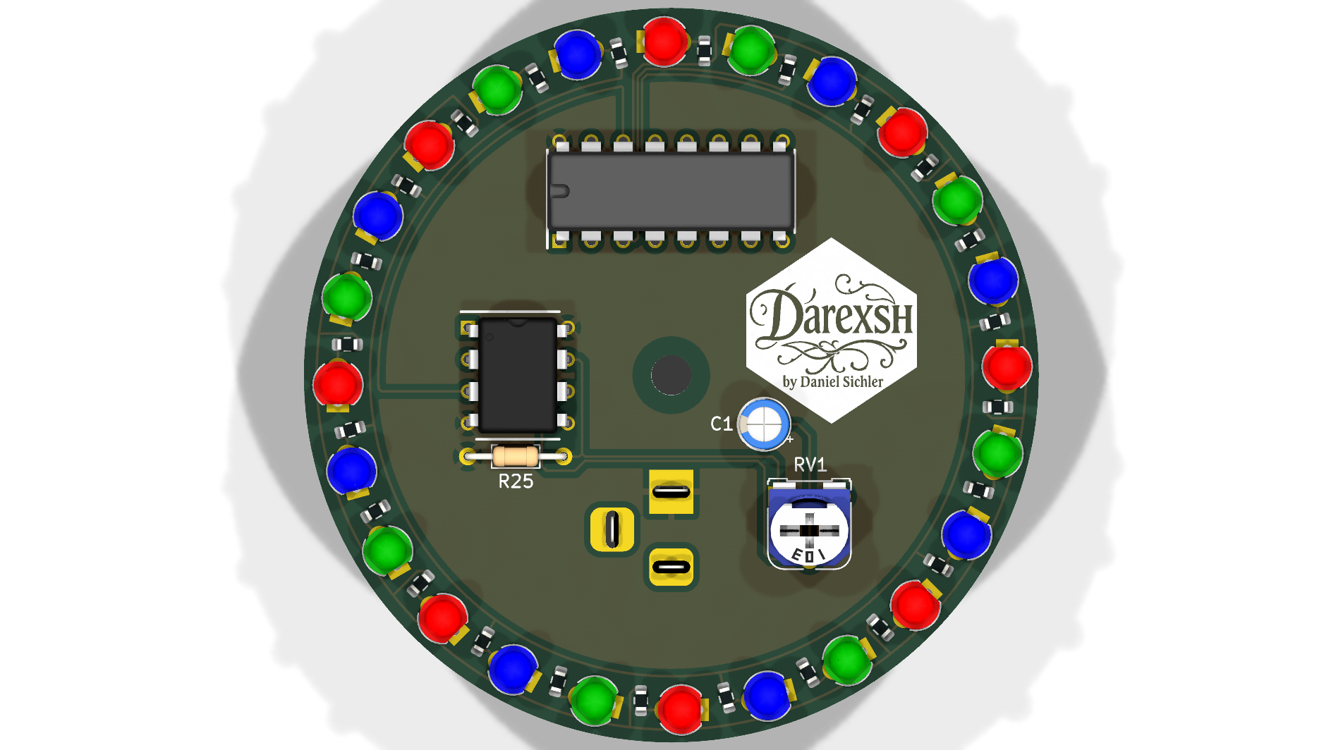
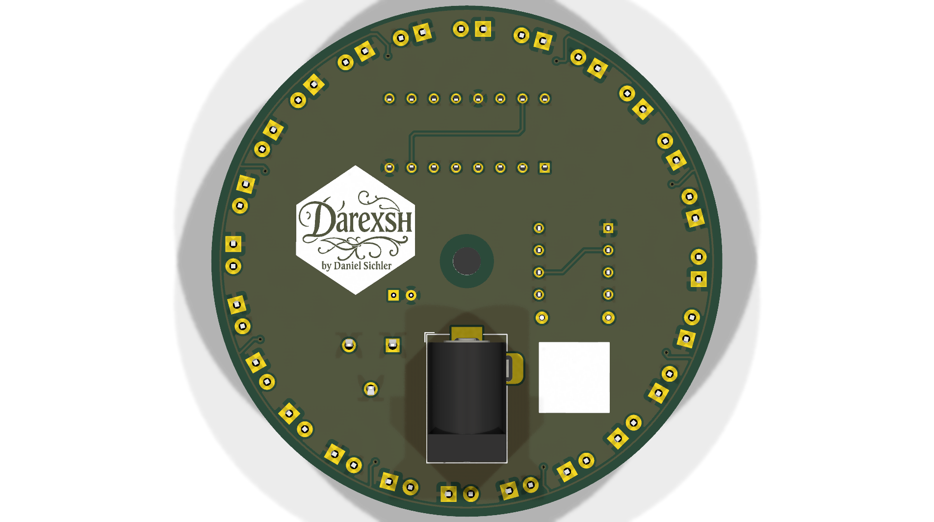
| Qty | Value | Footprint | References |
|---|---|---|---|
| 24 | 680R | Resistor_SMD:R_0603_1608Metric | R1, R2, R10, R11, R12, R13, R14, R15, R16, R17, R18, R19, R20, R21, R22, R23 +8 |
| 8 | LED_BLUE | LED_THT:LED_D3.0mm | D17, D18, D19, D20, D21, D22, D23, D24 |
| 8 | LED_GREEN | LED_THT:LED_D3.0mm | D9, D10, D11, D12, D13, D14, D15, D16 |
| 8 | LED_RED | LED_THT:LED_D3.0mm | D1, D2, D3, D4, D5, D6, D7, D8 |
| 2 | LOGO | ProjectFootprints:logo | G***, G*** |
| 1 | 10k | Resistor_THT:R_Axial_DIN0204_L3.6mm_D1.6mm_P7.62mm_Horizontal | R25 |
| 1 | 10k_Poti | Potentiometer_THT:Potentiometer_Runtron_RM-065_Vertical | RV1 |
| 1 | 10uF/25V | Capacitor_THT:CP_Radial_D4.0mm_P2.00mm | C1 |
| 1 | Barrel_Jack_Switch | Connector_BarrelJack:BarrelJack_Horizontal | J1 |
| 1 | CD4017BE | ProjectFootprints:CD4017BE | IC1 |
| 1 | MountingHole | MountingHole:MountingHole_3.2mm_M3 | H1 |
| 1 | NE555P | ProjectFootprints:NE555P | IC2 |
Darexsh/RGB-Ringlight
Discrete RGB LED chaser ring powered by an NE555 astable clock and CD4017 counter. 24 LEDs arranged in a circular RGB sequence with variable chase speed.

Ismael034/ulp_daughterboard
KiCad project files for a hardware CTF challenge used during the 2026 ULP CTF. The board is meant to be used with the ch32v203-dev development board.


confusedCoyote/PCB-15cm-ruler
A Printed Circuit Board ruler with some helpful hints


Lichtwerkstatt/ElectronicTinkerStuff
A little Repository with all our small electronic projects

maheen-ahmed1/OptoTACH
Precision non-contact optical tachometer (0–9999 RPM/RPS) built entirely with discrete CMOS logic & 555 timers; no microcontroller, no firmware. Includes KiCad EDA, 3D model, Python simulation, and bench validation.


Sparkshiva007/LED-chaser-PCB
A simple LED chaser circuit using a 555 timer and CD4017 IC, designed in KiCad. It lights up LEDs in sequence like a running light effect.
It measures 29.2 × 1.5 mm and has 2 copper layers, 1.6 mm thick.
57 parts, built around the CD4017BE and NE555P. The full list of its parts is on this page, with links to each part's symbol and footprint where PCBKit's library has them.
From the Darexsh/RGB-Ringlight repository on GitHub, at the commit this page was made from: the board is Hardware/Project.kicad_pcb and its schematic Hardware/Project.kicad_sch. PCBKit opens the board in the browser, with nothing to install.
Its repository publishes it under the MIT licence: you may reuse it on that licence's terms (keep the author's notice, and for a copyleft licence share your changes alike).