4 layers129 × 104.6 mm

 DanielMartensson/STM32-PLC183
STM32 microcontroller with lots of periferials such as ADC, differential ADC, Input Capture, PWM, USB, Encoder, DAC, Digital Input, RTC, CAN-bus + Alarm etc.
DAC ADC PWM IO is an open-source printed circuit board by DanielMartensson, from the DanielMartensson/STM32-PLC repository on GitHub, published under the MIT licence. It is a 4-layer board of 100 × 100 mm with 270 parts on 208 nets, routed with 2,023 tracks and 1,032 vias.
It is built around the TCAN332D, LM2902 and LM2904, with the BZX84C3V6LT1G-TP, BUK9M15-60EX and BC847C-QR among its other parts. Its parts include 124 resistors, 44 diodes, 36 capacitors, 30 fuses and 11 transistors. It belongs with the audio and music and interfaces and adapters boards and the STM32 boards of this library.


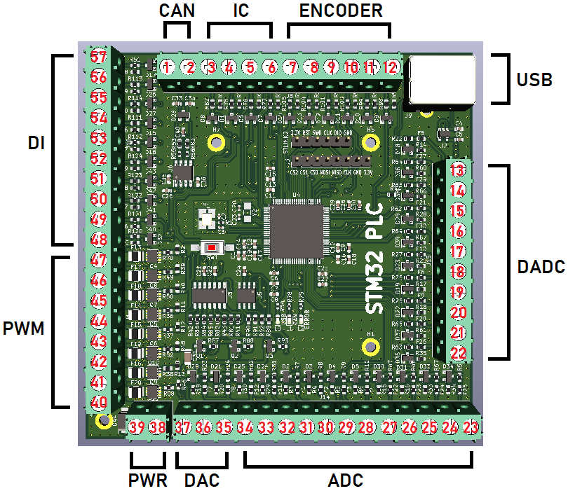
This project is a PCB bord that has the following measurement and control input/output:
The documentation for the pin map can be found in the Documentation folder. Also all the article numbers for each component can be found in at the DAC ADC PWM IO.sch file in the PCB folder. Just double click on a PCB symbol and see the Mouser Electronics article number of the electrical component.
Yes, it's possible to set the calibration to each input in this project. You need to have the ILI9341 touch LCD with SPI bus. Open the STM32 PLC Pinouts.pdf and see the connection for the LCD. You can also set the PWM frequency and analog input gain for the ADC and Differential ADC at 16-bit.
The STM32 PLC has internal SAE J1939 protocol. Made from Open-SAE-J1939 repository.
This is a QT C++ software that you can connect to your STM32 PLC board via the USB and then you can send signals from OpenSourceLogger and recieve signals. OpenSourceLogger is a very easy to use logging and controlling software and it stores data at a SQL server.
This is a ImGui C++ project that do the same as OpenSourceLogger, but it's much better and have more features. The reason why I moved away from QT C++ to ImGui C++ is because it's much easier to write a GUI application in C++ by using ImGui instead of QT. With QT, you are stuck with object oriented programming. Everything is a class. But for ImGui, you can choose which type of lever you want to code, I prefer C-style C++ code with a small dose of object oriented programming (if needed).
Consider that I will work on GoobySoft instead of OpenSourceLogger.
The STM32 PLC has a lot of functions you can select by touching the LCD.
PCB folder and open the .pro file with KiCAD and greate a gerber file of your own choicegerber file and let them produce the board for youMouser ElectronicsCode project and import the .ioc project file using STM32CubeIDEC code by using ST-Link V2 connectionIt's done. I don't plan to update this project. Everything is working and it will remain that way.
| Qty | Value | Footprint | References |
|---|---|---|---|
| 61 | 10k | Resistor_SMD:R_0603_1608Metric | R11, R100, R101, R102, R103, R104, R105, R106, R107, R108, R109, R110, R111, R112, R113, R114 +45 |
| 54 | 160 | Resistor_SMD:R_0603_1608Metric | R10, R14, R15, R16, R17, R18, R19, R20, R21, R22, R23, R24, R25, R26, R27, R28 +38 |
| 42 | BZX84C3V6LT1G | Diode_SMD:D_SOT-23_ANK | D1, D2, D10, D11, D12, D13, D14, D15, D16, D17, D18, D19, D20, D21, D22, D23 +26 |
| 22 | Max 30mA | Fuse:Fuse_0603_1608Metric | F1, F2, F3, F10, F11, F12, F21, F22, F23, F24, F25, F26, F27, F28, F29, F30 +6 |
| 11 | 10nF | Capacitor_SMD:C_0603_1608Metric | C10, C12, C16, C17, C25, C28, C33, C34, C35, C36, C40 |
| 10 | 100nF | Capacitor_SMD:C_0603_1608Metric | C1, C6, C7, C11, C13, C21, C22, C24, C26, C29 |
| 8 | BUK9M15-60EX | Package_TO_SOT_SMD:LFPAK33 | Q4, Q5, Q6, Q7, Q8, Q9, Q10, Q11 |
| 8 | Max 2.5A | Fuse:Fuse_1210_3225Metric | F13, F14, F15, F16, F17, F18, F19, F20 |
| 7 | 1uF | Capacitor_SMD:C_0603_1608Metric | C4, C5, C9, C14, C18, C19, C27 |
| 4 | MountingHole_Pad | MountingHole:MountingHole_2.7mm_M2.5_DIN965_Pad | H1, H5, H6, H7 |
| 3 | 220 | Resistor_SMD:R_0402_1005Metric | R54, R78, R79 |
| 3 | 4.7uF | Capacitor_SMD:C_0603_1608Metric | C8, C15, C30 |
| 3 | BC847C-QR | Package_TO_SOT_SMD:SOT-23 | Q1, Q2, Q3 |
| 2 | 0 | Resistor_SMD:R_0402_1005Metric | R55, R56 |
| 2 | 10pF | Capacitor_SMD:C_0402_1005Metric | C2, C3 |
| 2 | 4.7pF | Capacitor_SMD:C_0402_1005Metric | C20, C23 |
| 2 | 60 | Resistor_SMD:R_0603_1608Metric | R53, R83 |
| 2 | Screw_Terminal_01x9 | TerminalBlock_Phoenix:TerminalBlock_Phoenix_PT-1,5-9-5.0-H_1x09_P5.00mm_Horizontal | J1, J16 |
| 1 | 1.5k | Resistor_SMD:R_0603_1608Metric | R44 |
| 1 | 10uF | Capacitor_SMD:C_1206_3216Metric | C31 |
| 1 | 2k | Resistor_SMD:R_0402_1005Metric | R1 |
| 1 | AP7343-33W5-7 | Package_TO_SOT_SMD:SOT-23-5 | U2 |
| 1 | Battery_Cell | Battery:BatteryHolder_Keystone_3002_1x2032 | BT1 |
| 1 | Conn_01x08 | Connector_PinHeader_2.54mm:PinHeader_1x08_P2.54mm_Vertical | J3 |
| 1 | HSE | Crystal:Crystal_SMD_3225-4Pin_3.2x2.5mm_HandSoldering | Y1 |
| 1 | LED_CAN_RX_TX | LED_SMD:LED_0603_1608Metric | L1 |
| 1 | LED_ERROR | LED_SMD:LED_0603_1608Metric | L2 |
| 1 | LED_USB_RX_TX | LED_SMD:LED_0603_1608Metric | L0 |
| 1 | LM2902 | Package_SO:SOIC-14_3.9x8.7mm_P1.27mm | U3 |
| 1 | LM2904 | Package_SO:SOIC-8_3.9x4.9mm_P1.27mm | U5 |
| 1 | LSE | Crystal:Crystal_SMD_EuroQuartz_EQ161-2Pin_3.2x1.5mm_HandSoldering | Y2 |
| 1 | PESD5V0L2BT,215 | Package_TO_SOT_SMD:SOT-23 | D28 |
| 1 | SK56A-LTP | Diode_SMD:D_SMA | D44 |
| 1 | ST-Link V2 connetor | Connector_PinHeader_2.54mm:PinHeader_1x06_P2.54mm_Vertical | STLINK2 |
| 1 | STM32F373VBTx | Package_QFP:LQFP-100_14x14mm_P0.5mm | U4 |
| 1 | SW_Push | Button_Switch_SMD:SW_SPST_FSMSM | SW1 |
| 1 | Screw_Terminal_01x02 | TerminalBlock_Phoenix:TerminalBlock_Phoenix_PT-1,5-2-5.0-H_1x02_P5.00mm_Horizontal | J2 |
| 1 | Screw_Terminal_01x10 | TerminalBlock_Phoenix:TerminalBlock_Phoenix_PT-1,5-10-5.0-H_1x10_P5.00mm_Horizontal | J15 |
| 1 | Screw_Terminal_01x12 | TerminalBlock_Phoenix:TerminalBlock_Phoenix_PT-1,5-12-5.0-H_1x12_P5.00mm_Horizontal | J8 |
| 1 | Screw_Terminal_01x15 | TerminalBlock_Phoenix:TerminalBlock_Phoenix_PT-1,5-15-5.0-H_1x15_P5.00mm_Horizontal | J14 |
| 1 | TCAN332 | Package_SO:SOIC-8_3.9x4.9mm_P1.27mm | U6 |
| 1 | USB_B | Connector_USB:USB_B_OST_USB-B1HSxx_Horizontal | J9 |


alimleahat/analog-audio-visualizer-pcb
Three-band analog audio visualizer built in KiCad for ELEC2101, with PCB files, assembly photos, and bench measurements.


VikingMotorsports/Battery-Management-System-Capstone-2026
The BMS Capstones deliverables


harp-tech/device.faststepper
A fast moving stepper motor controller device, with acceleration, jerk control, and end stop support
It measures 100 × 100 mm and has 4 copper layers, 1.6 mm thick.
270 parts, built around the TCAN332D, LM2902, LM2904 and BZX84C3V6LT1G-TP. The full list of its parts is on this page, with links to each part's symbol and footprint where PCBKit's library has them.
From the DanielMartensson/STM32-PLC repository on GitHub, at the commit this page was made from: the board is PCB/DAC ADC PWM IO.kicad_pcb and its schematic PCB/CAN.kicad_sch. PCBKit opens the board in the browser, with nothing to install.
Its repository publishes it under the MIT licence: you may reuse it on that licence's terms (keep the author's notice, and for a copyleft licence share your changes alike).