Skip to the content
2 layers37 × 20 mmMarauder mini pcb, the printed circuit board in 3D

Marauder mini pcb

Dade3e/Flipper_Esp327

Esp32S2 Flipper zero project

Size
37 × 20 mm
Copper layers
2
Thickness
1.6 mm
Parts
10
Nets
43
Pads
71
Tracks, vias
56, 7
Pours
1
Routed
Yes
KiCad
KiCad 7 (file 20221018)
Created
14 May 2023
Updated
3 Jul 2023

Overview

Marauder mini pcb is an open-source printed circuit board by Dade3e, from the Dade3e/Flipper_Esp32 repository on GitHub. It is a 2-layer board of 37 × 20 mm with 10 parts on 43 nets, routed with 56 tracks and 7 vias.

It is built around the ESP32-WROOM-32. Its parts include 3 switches, 2 capacitors, 2 resistors, 1 IC and 1 diode. It belongs with the ESP32 boards of this library.

Main components

1

README

README.md

Original Marauder code https://github.com/justcallmekoko/ESP32Marauder/releases/tag/v0.10.4

Original Deauth code https://github.com/SpacehuhnTech/esp8266_deauther/releases/tag/2.6.1

Hi, I use Esp-wroom-32, and to save pcap on flipper zero sd:

  • Software:

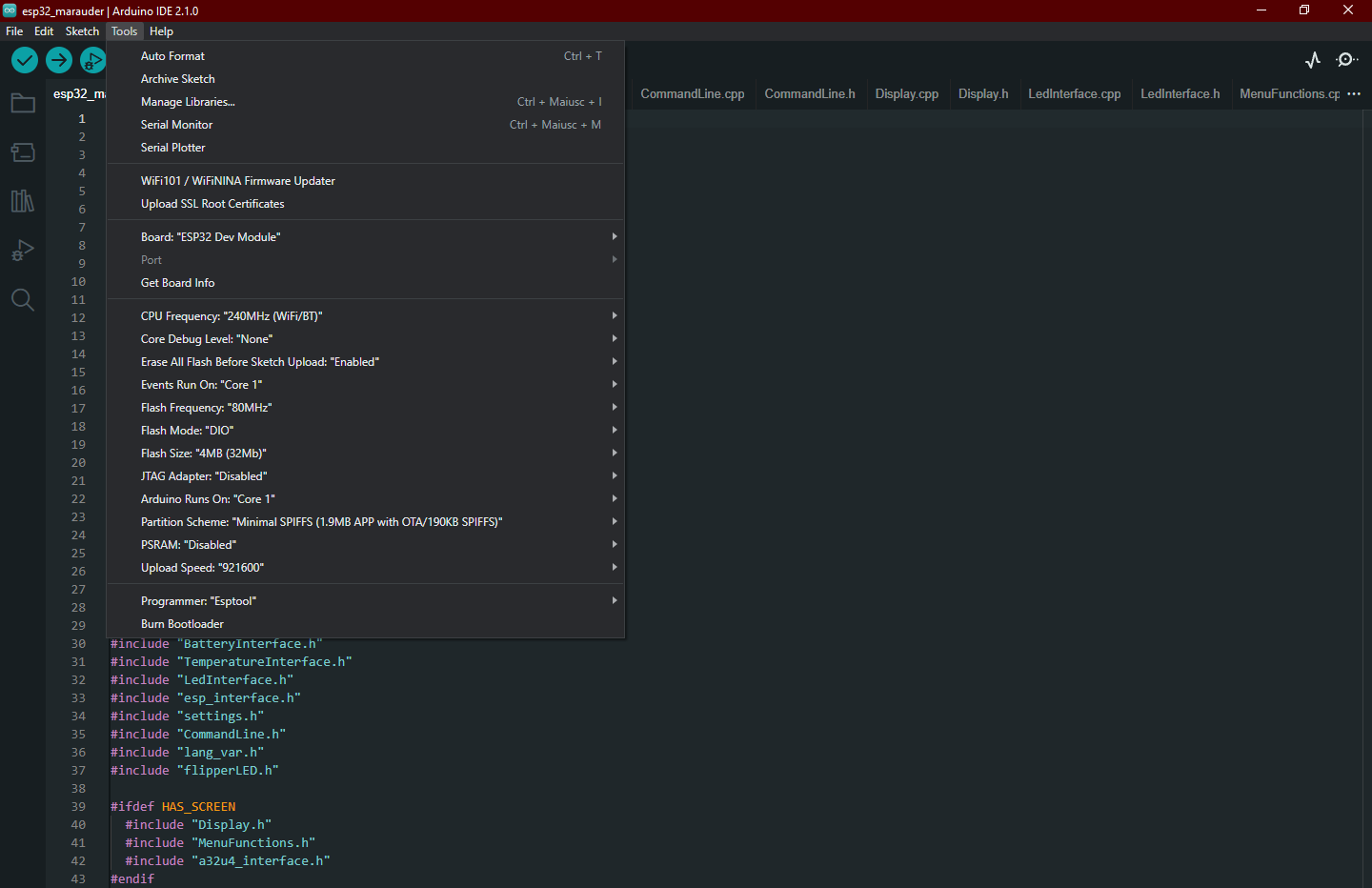
    • Update Arduino ide for recompile marauder esp32 firmware: Arduino Ide Version: 2.1.0;
    • And I configure it with this guide: https://github.com/justcallmekoko/ESP32Marauder/wiki/arduino-ide-setup ;
    • In the marauder project (version 0.10.3), in config.h, uncomment #define WRITE_PACKETS_SERIAL;
    • uncomment #define GENERIC_ESP32 and comment the others;
    • ADD in //// SD DEFINITIONS:
      text
      #ifdef GENERIC_ESP32
        #define SD_CS 5
      #endif
    • in esp32_marauder.ino, modify Serial1 with the serial you want to use: ex. Serial2 in my case:
      text
      #ifdef WRITE_PACKETS_SERIAL
          // Starts a second serial channel to stream the captured packets
          Serial2.begin(115200);
        #endif
    • In Buffer.cpp modify all Serial1.write in void Buffer::forceSaveSerial() function with your Serial: Serial2
  • Hardware: I connect:

    • Esp32 RX0 => pin13/TX Flipper zero,
    • ESP32 TX0 0> pin14/RX,
    • RX2 => pin15/C1,
    • TX2 => pin16/C0,
    • Vin ESP32 pin to 5V Flipper zero pin, to be enabled in the main GPIO section,
    • GND Esp32 pin to GND Flipper zero pin

I think this is all :/

Settings arduino ide

Parts

10
QtyValueFootprintReferences
2CCapacitor_SMD:C_0805_2012Metric_Pad1.18x1.45mm_HandSolderC1, C2
2SW_PushButton_Switch_SMD:SW_SPST_EVQPE1SW2, SW3
110KCapacitor_SMD:C_0805_2012Metric_Pad1.18x1.45mm_HandSolderR2
1Conn_01x10Library:PinHeader_1x10_P2.54mm_Vertical_largoJ1
1ESP32-WROOM-32RF_Module:ESP32-WROOM-32UU1
1LEDCapacitor_SMD:C_0805_2012Metric_Pad1.18x1.45mm_HandSolderD1
1RCapacitor_SMD:C_0805_2012Metric_Pad1.18x1.45mm_HandSolderR1
1SW_SPDTButton_Switch_SMD:SW_SPDT_PCM12SW1

More from Dade3e/Flipper_Esp32

3
  • 2 layers32 × 21.3 mmF0 MyCompass, the printed circuit board in 3D

    F0 MyCompass

    Dade3e/Flipper_Esp32

    Esp32S2 Flipper zero project

    9 parts7
  • 2 layers27.8 × 22 mmCc1101 pcb, the printed circuit board in 3D

    Cc1101 pcb

    Dade3e/Flipper_Esp32

    Esp32S2 Flipper zero project

    8 parts7
  • 2 layers28 × 20 mmMarauder mini pcb, the printed circuit board in 3D

    Marauder mini pcb

    Dade3e/Flipper_Esp32

    Esp32S2 Flipper zero project

    8 parts7

Similar boards

  • 2 layers24.1 × 36.2 mmEsp32miniBT, the printed circuit board in 3D

    Esp32miniBT

    asterics/esp32_mouse_keyboard

    ESP32 implementation for HID over GATT Keyboard and Mouse (Bluetooth Low Energy). Including serial API for external modules (similar to Adafruit EZKey HID)

    28 parts911GPL-3.0
  • 4 layers99.6 × 76.2 mmE TKT, the printed circuit board in 3D

    E TKT

    andreisperid/E-TKT

    open source embossed label maker

    110 parts481MIT
  • 4 layers46.8 × 34.8 mmSmartWatch V4, the printed circuit board in 3D

    SmartWatch V4

    Bellafaire/ESP32-Smart-Watch

    An open source smartwatch based on the ESP32 compatible with the Arduino IDE.

    74 parts258MIT
  • 2 layers90 × 76.5 mmLCDZapperPro, the printed circuit board in 3D

    LCDZapperPro

    charcole/LCDZapper

    Device for making light gun games playable on LCD TVs

    126 parts163
  • 2 layers57.2 × 35.1 mmMainBoard Rev2, the printed circuit board in 3D

    MainBoard Rev2

    lzrtag/LZRTag

    AVR-Based easily modifyable DIY Lasertag!

    70 parts111GPL-3.0
  • 2 layers85 × 56 mmHB RF ETH, the printed circuit board in 3D

    HB RF ETH

    alexreinert/PCB

    Some of my PCBs

    96 parts104
  • 2 layersSmp7c, the printed circuit board in 3D

    Smp7c

    likeablob/slow-movie-player-7c

    Yet another "Slow Movie Player" implementation with 7-color E-Paper module and ESP32.

    18 parts51MIT
  • 2 layers30.8 × 24.4 mmWii Bluetooth Replacement, the printed circuit board in 3D

    Wii Bluetooth Replacement

    JSnowden33/Wii-Bluetooth-Replacement

    This project is a full replacement for the Nintendo Wii's Bluetooth module. Emulation of the Bluetooth module is performed on the PIC32 based on rnconrad's emulator, while controller connectivity on the ESP32 is based…

    50 parts48GPL-3.0

Questions

How big is the Marauder mini pcb PCB?

It measures 37 × 20 mm and has 2 copper layers, 1.6 mm thick.

What parts does the Marauder mini pcb use?

10 parts, built around the ESP32-WROOM-32. The full list of its parts is on this page, with links to each part's symbol and footprint where PCBKit's library has them.

Where can I download the Marauder mini pcb KiCad files?

From the Dade3e/Flipper_Esp32 repository on GitHub, at the commit this page was made from: the board is marauder_mini_pcb_2/marauder_mini_pcb.kicad_pcb and its schematic MyCompass/F0_MyCompass/F0_MyCompass.kicad_sch. PCBKit opens the board in the browser, with nothing to install.

Can I use the Marauder mini pcb design in my own project?

Its repository states no licence, so its author keeps all rights: ask Dade3e before reusing the design.