4 layers65 × 70 mm

 DVDPlayer/SCB55Teensy2cw
MIDI control board with display to support the Roland SCB-55 card
SCB55 Teensy2 is an open-source printed circuit board by DVDPlayer, from the DVDPlayer/SCB55Teensy2cw repository on GitHub, published under the GPL-3.0 licence. It is a 2-layer board of 137 × 89 mm with 34 parts on 55 nets, routed with 303 tracks and 0 vias.
It is built around the IA0512S, TSR 1-2450E and H11L1. Its parts include 7 capacitors, 6 resistors, 5 ICs, 5 connectors and 3 diodes. It belongs with the audio and music boards and the AVR (ATmega, ATtiny) boards of this library.


Disclaimer: I'm not a professional programmer or hardware engineer, so go easy on me, use at own risk!
Note: I know that the Teensy 2.0 is quite old, but I used it because I had it and for the challenge! Feel free to port it to another device. (Teensy 2.0 also has built-in support for USB-MIDI)
A playback prioritizing serial and USB MIDI firmware for the Teensy 2.0 platform featuring an OLED user interface, rotary encoder control (variable acceleration), Capital Tone Fallback (inverts bank# on fallback), drum and instrument tracking / setting per channel (354 instruments & 10 drum sets - all banks except 126), channel level settings (volume, reverb, chrous), global level settings (volume reverb, chrous), MT-32 emulation initialization (patch, pan, reverb, & pitch bend), display of MT-32 / SC-55 SysEx text messages, display of SC-55 SysEx graphics, send / receive GM & GS SysEx reset, 'analog' volume setting, all notes off Panic! feature, external (software driven) reset button, power-on reset of SCB-55, inactivity screen saver, and a dedicated MIDI hardware pipeline to the SCB-55 waveblaster module.
Runs from USB (<350mA) or dedicated 6Vdc to 35Vdc input. (see Teensy MOD picture)
This repository contains only the core project firmware and hardware. All third-party dependencies are managed locally to keep the repository structure clean and as lightweight as possible.
Before compiling, make sure you have the following libraries installed via the Arduino Library Manager:
Note: Core libraries (Arduino.h, Wire.h, avr/pgmspace.h, util/delay.h) are built into the Teensy / AVR toolchain and do not need to be installed manually.
To successfully fit the compiled firmware within the microcontroller's limited flash memory, you must disable the default Adafruit splash screen to save code space.
This project is shared under the GNU GPLv3 license, and since third-party libraries are not hosted directly in this repository, you will need to apply the following optimizations to your local Arduino environment manually:
Documents/Arduino/libraries/).Adafruit_SSD1306 directory.Adafruit_SSD1306.h in a text editor. // Uncomment to disable Adafruit splash logo
#define SSD1306_NO_SPLASHusb_api.h in a text editor and change #define USB_MIDI_SYSEX_MAX 64 to at least 79(Location example: c:\users\<username>\AppData\Local\Arduino15\packages\teensy\hardware\avr\1.61.0\cores\usb_midi)
Go back one directory to the cores folder and open the teensy folder and Edit HardwareSerial.cpp
Find and change the following two lines: (Note: RX_BUFFER_SIZE was 64 which is too small for long SysEx)
#define RX_BUFFER_SIZE 128
#define SERIAL1_TX_BUFFER_SIZE 256Board:Teensy2.0 USB Type:MIDI).Connect your components to the Teensy 2.0 board according to the pinout layout below:
| Component | Pin | Teensy 2.0 Pin | Notes |
|---|---|---|---|
| SSD1306 OLED | GND | GND | (Check pinout as some OLEDs are backwards!) |
| VCC 5V | VCC 5V | ||
| SCL | 5 (PD0) | I2C Clock (Wire.h) | |
| SDA | 6 (PD1) | I2C Data (Wire.h) | |
| Rotary Encoder | Pin A | 1 (PB1) | Main rotation pin |
| encoder module used | Pin B | 24* (PE6) | Main rotation pin |
| Switch | 0 (PB0) | Encoder push-button switch | |
| VCC | VCC | ||
| GND | GND | ||
| Vol POT 10k-100k | Wiper Pin | 12 (PD7) | 'Analog' Output Control (Volume potentiometer) |
| Right Pin | VCC | VCC | (optional part) |
| Left Pin | GND | GND | |
| Reset Button | Switch Pin | 10 (PC7) | System Reset trigger |
| GND | GND | (optional part) | |
| Reset to SCB55 | Reset Line | 2 (PB2) | Hardware reset line sent to SCB-55 - pin 26 |
| Serial MIDI RX | MIDI IN Line | RX (Pin 7) | (PD2) Hardware MIDI input (from H11L1+470Ω pull-up) |
| SCB-55 MIDI RX | MIDI OUT Line | TX (Pin 8) | (PD3) MIDI stream to Roland SCB-55 - pin 4 |
Note: Pin numbers are programming numbers, add 2 for actual pin number except 24 = pin30, 12 = pin19. If you want to use external power and USB, the Teensy 2.0 must be modified. (see Teensy MOD picture) The SCB-55 also requires a +/-12V and +5 supply to run correctly along with L/R audio out.
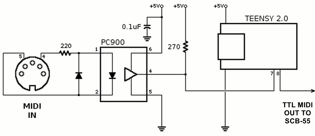
MIDI Input Example:
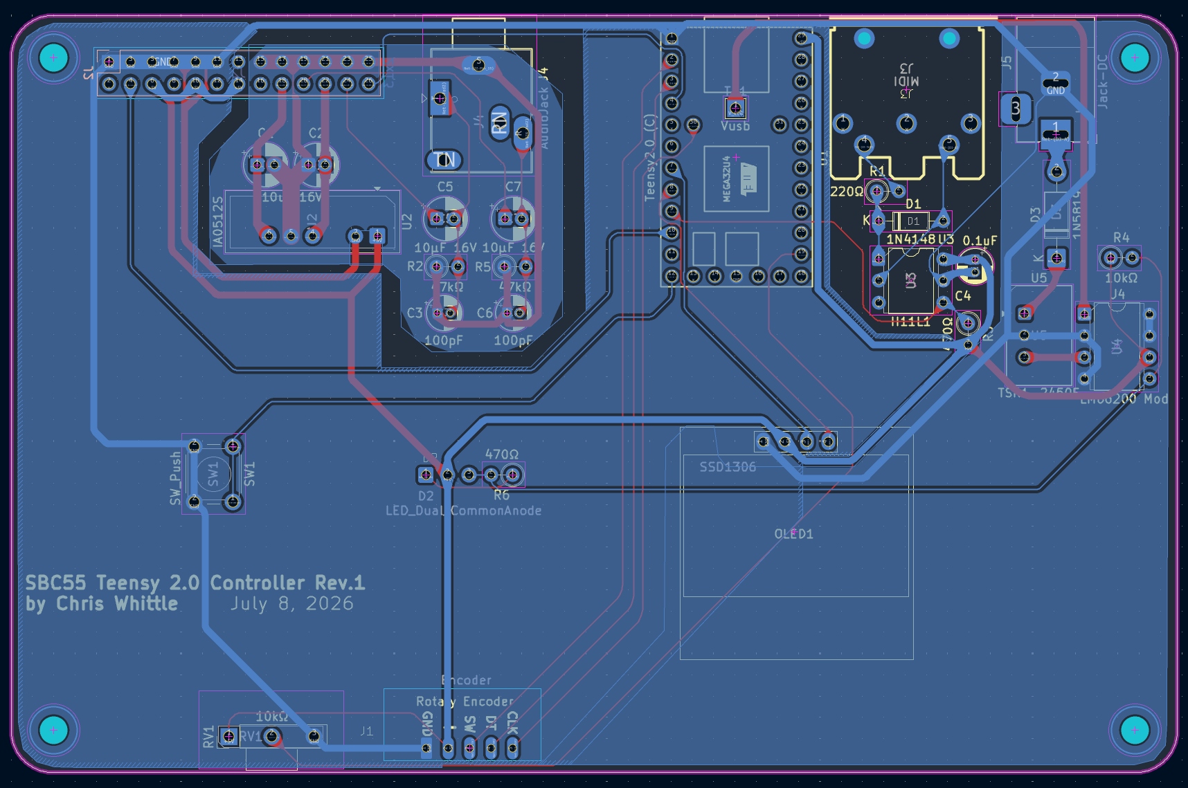
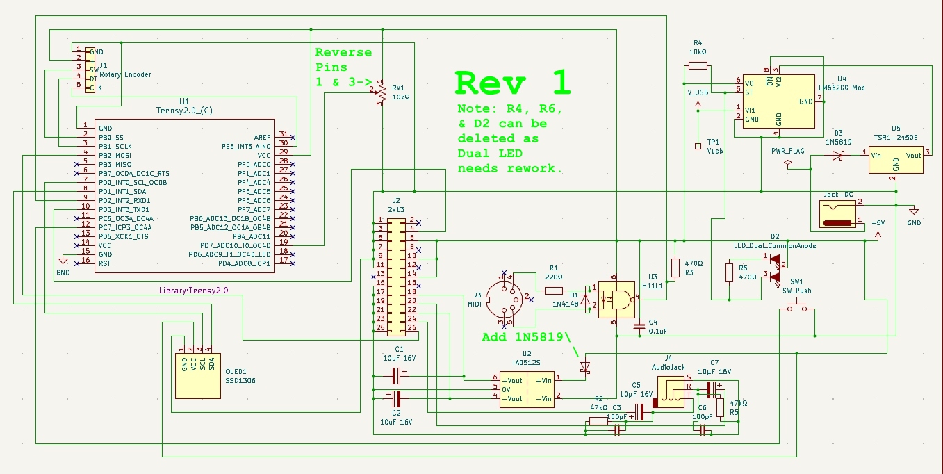
Arduino IDE Settings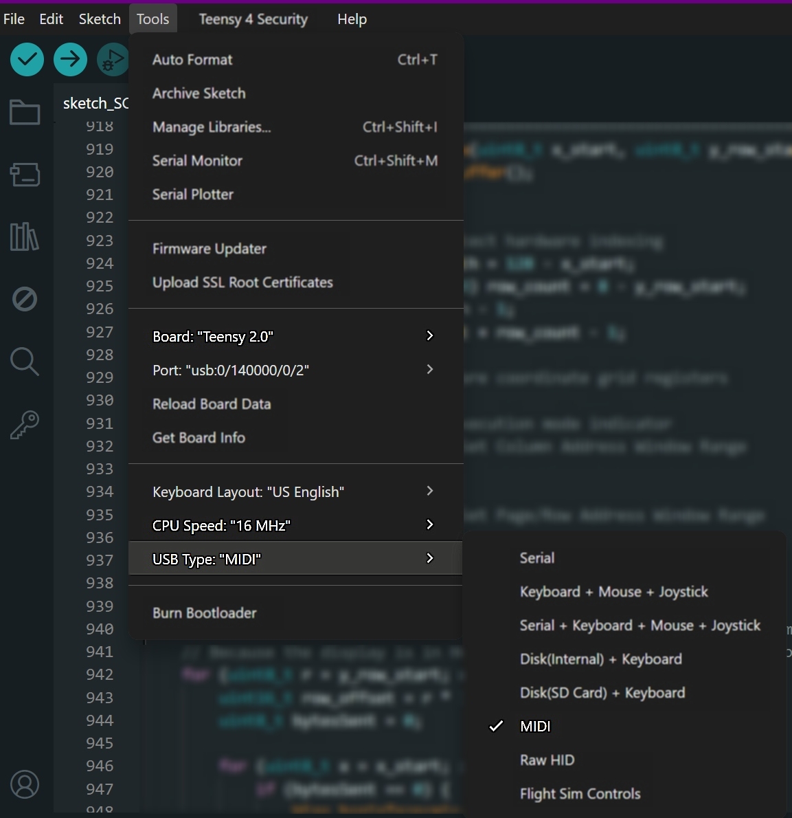 Hardware
 User Interface
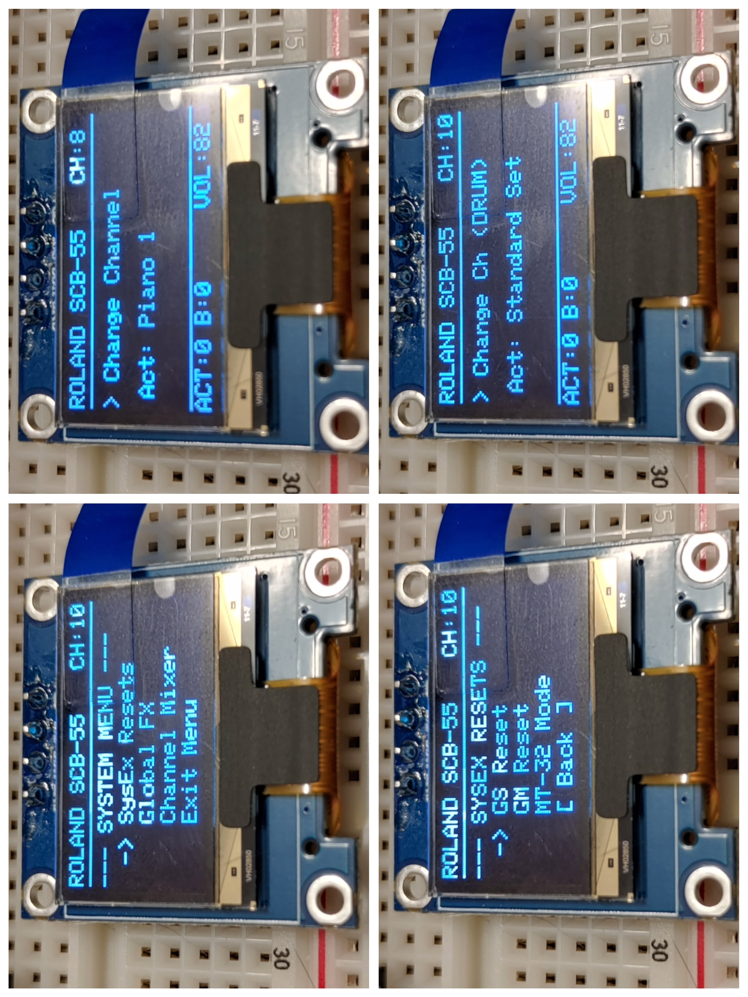 | 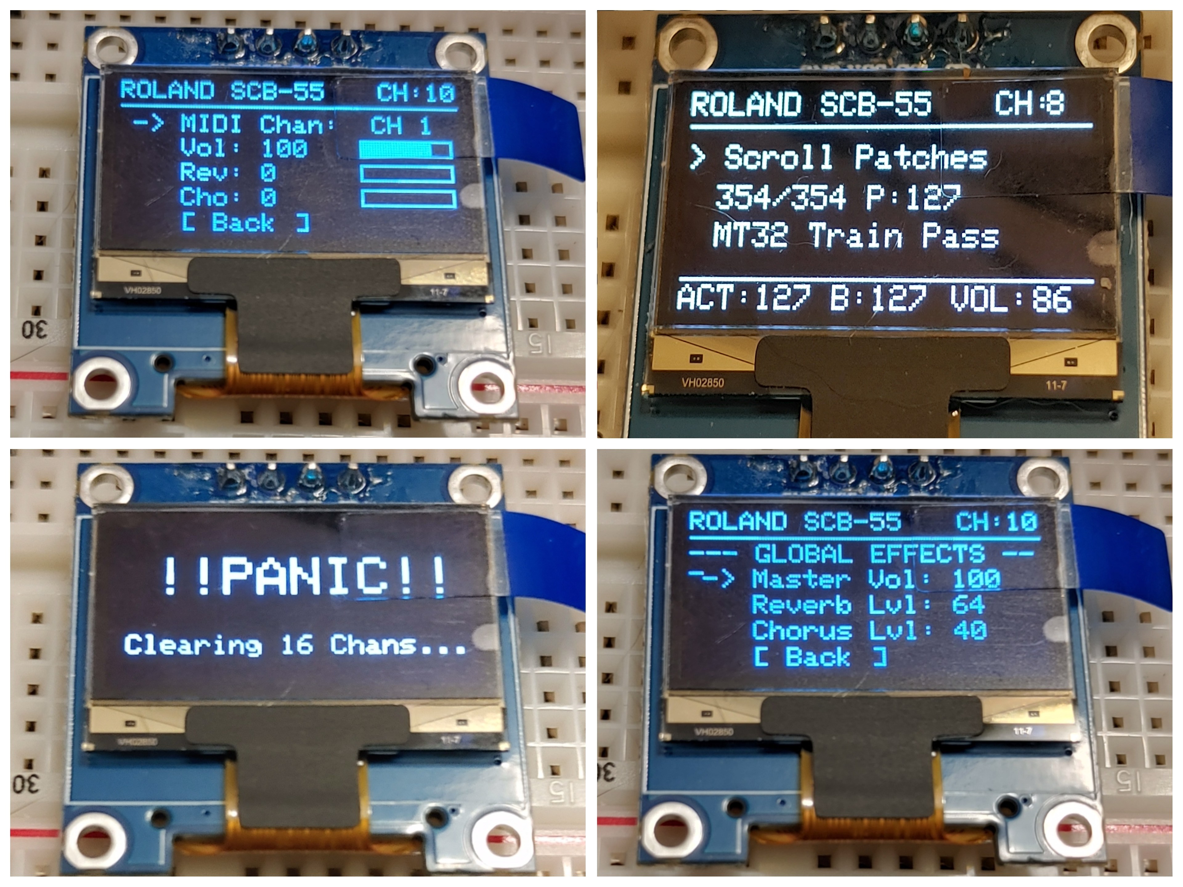 |
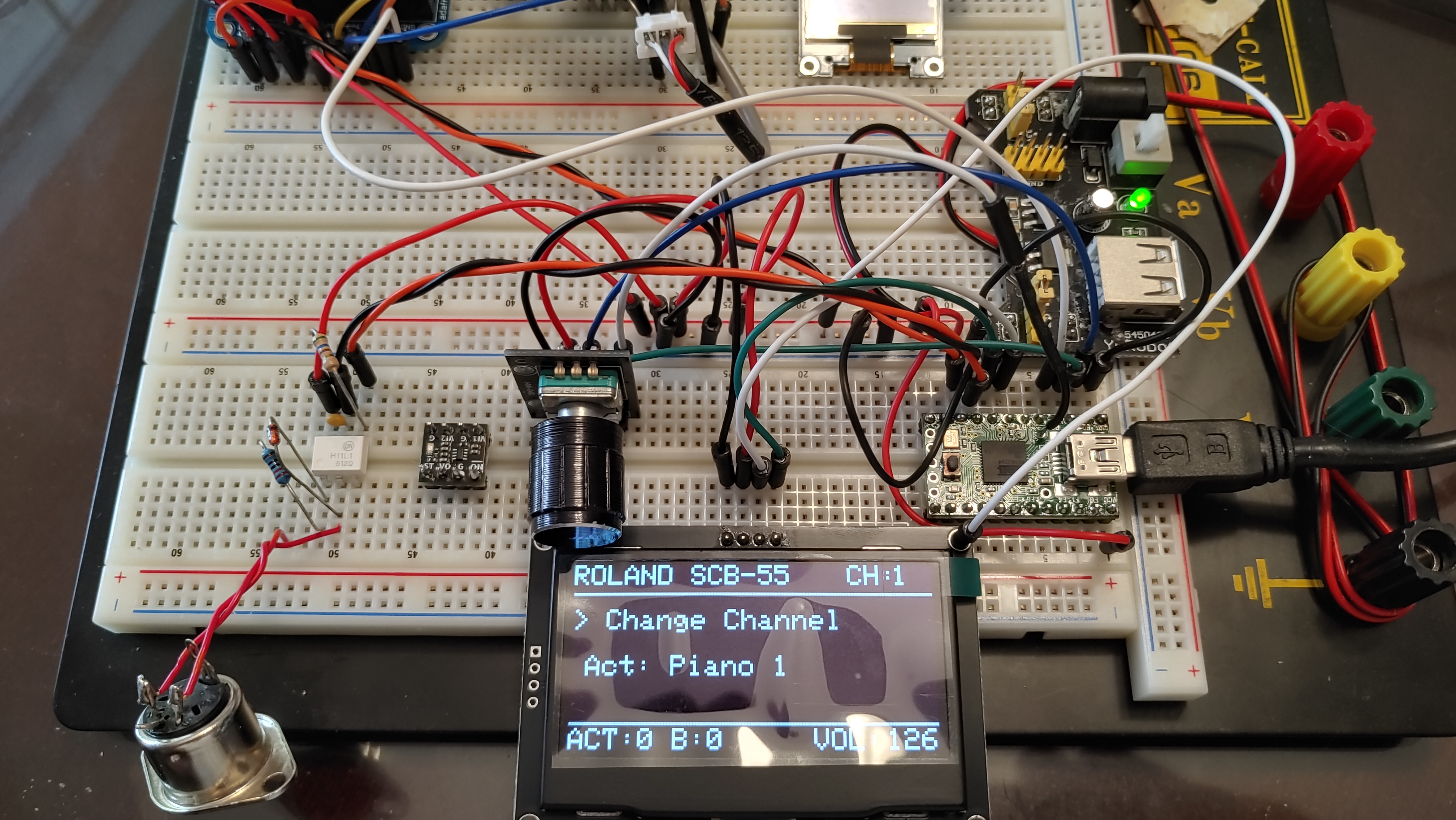
Important if using dual power (*Teensy MOD) 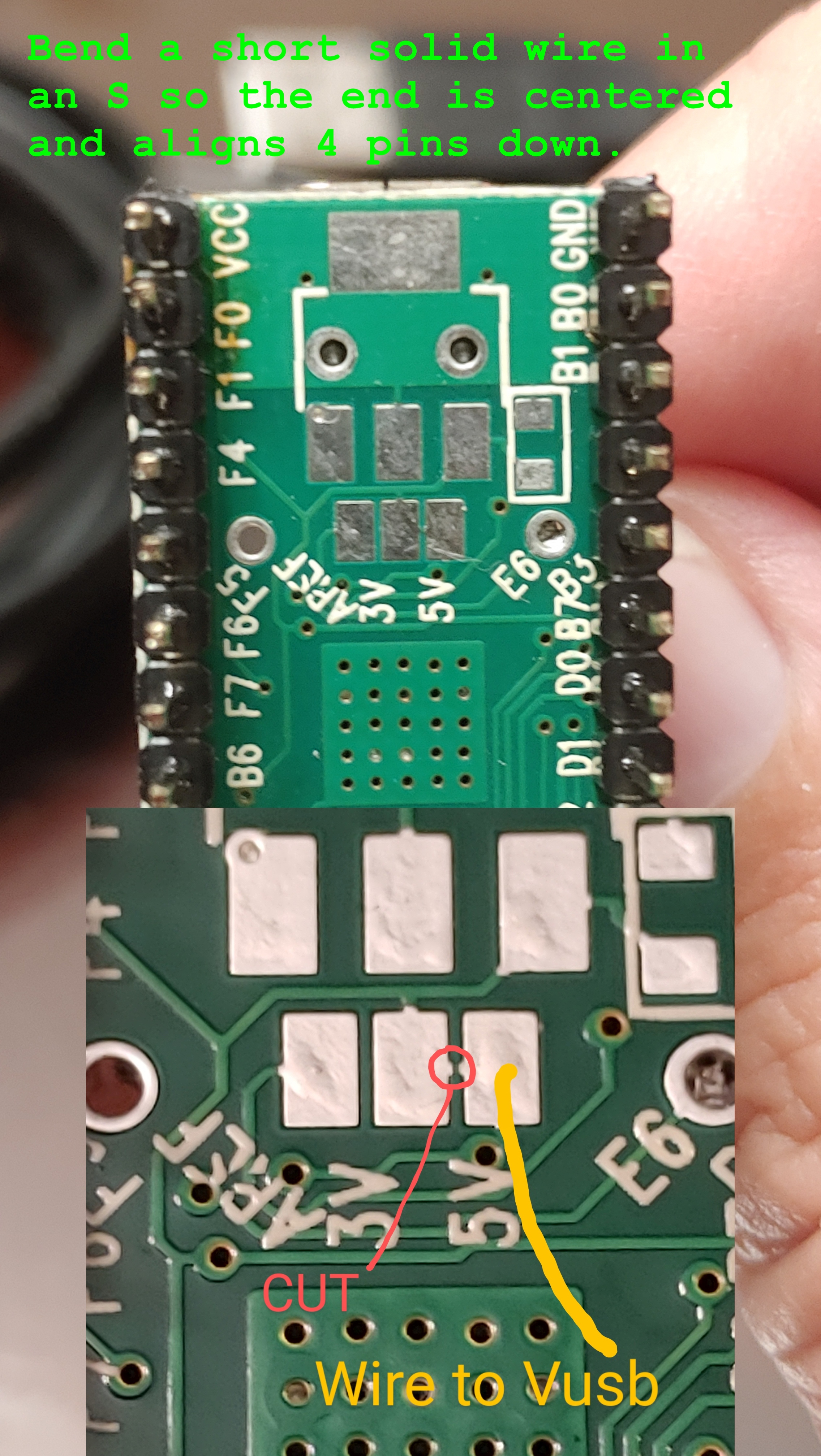 Initial Prototype
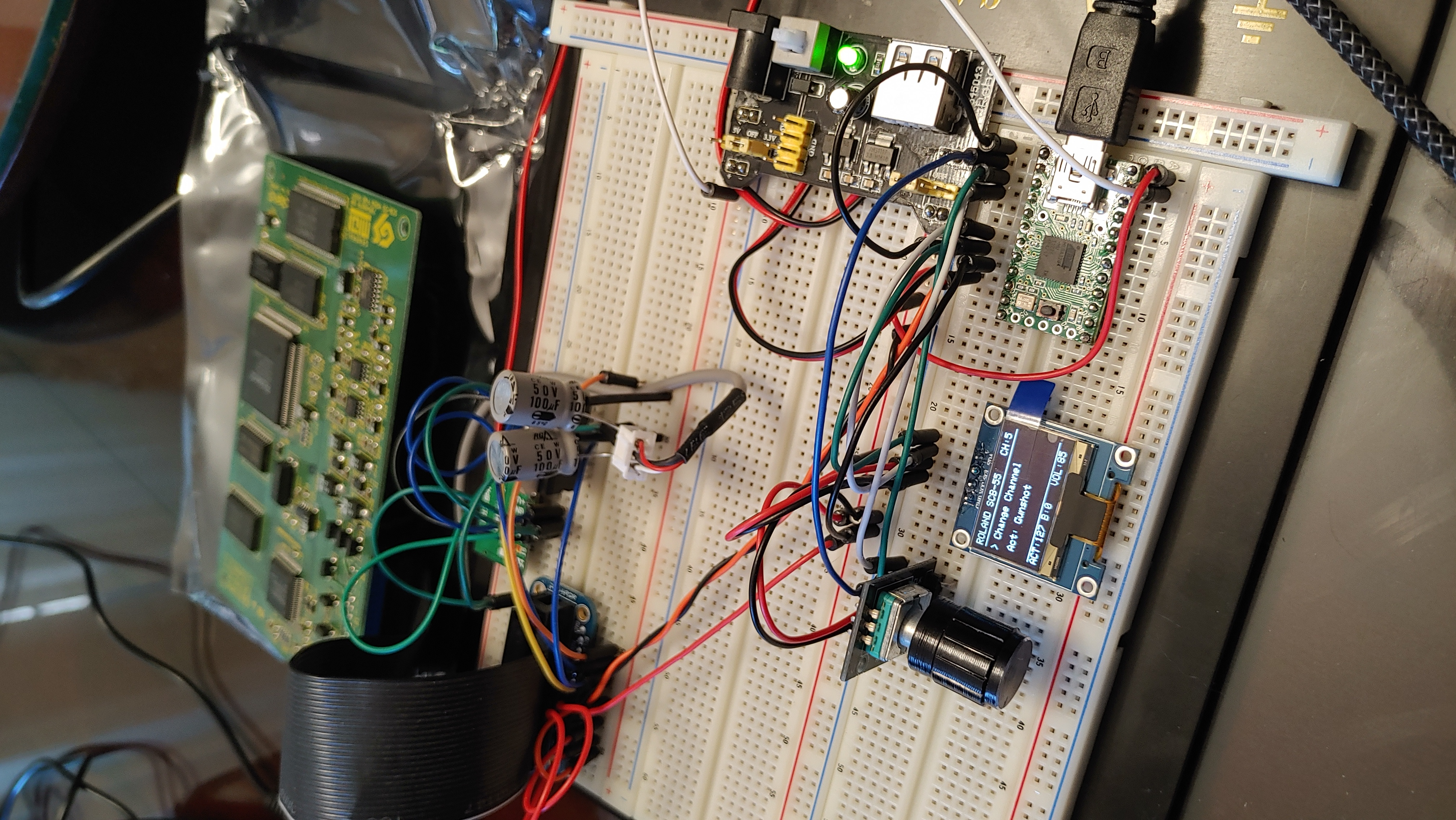
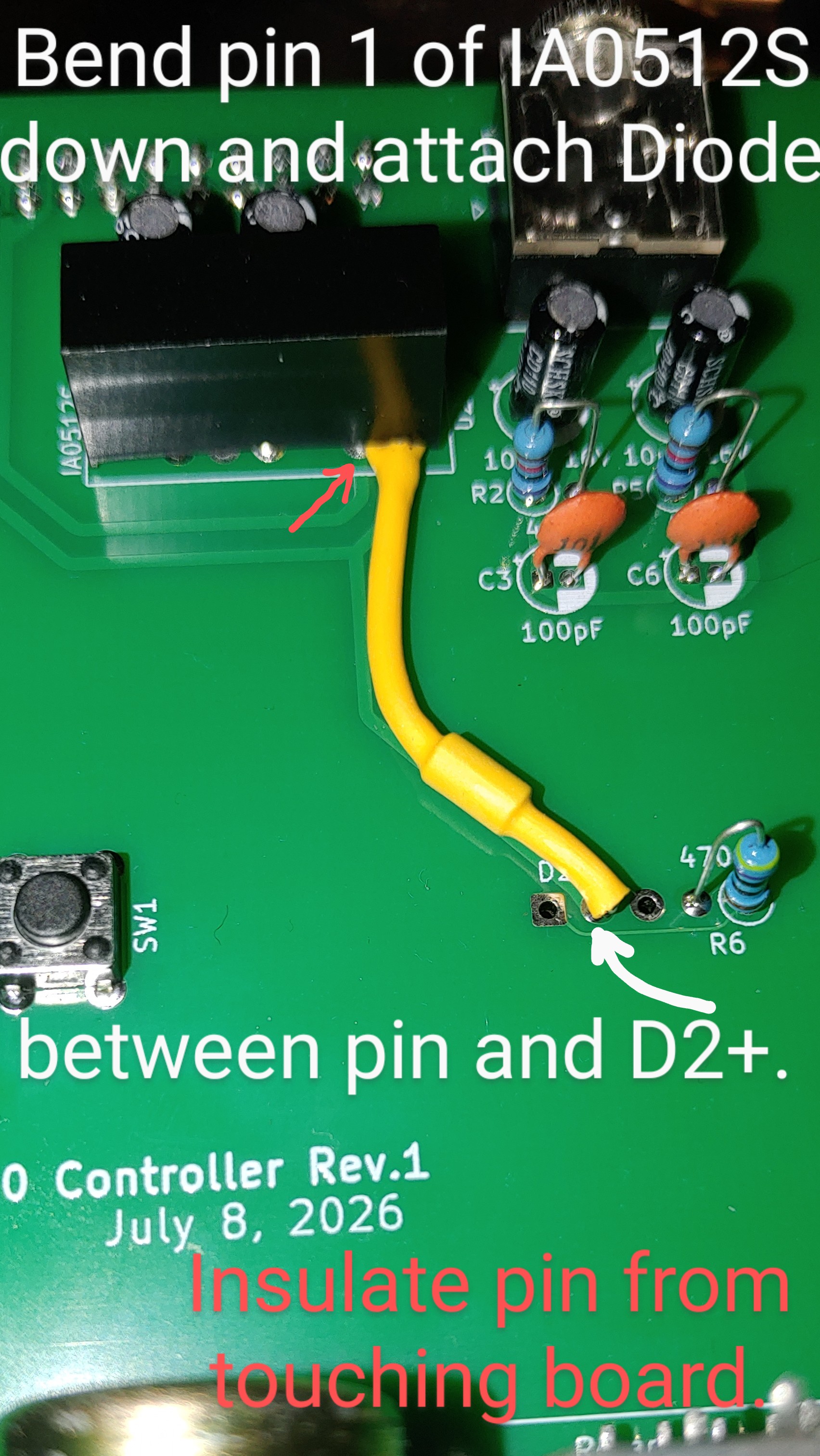
 If using rev1 hardware (update coming)
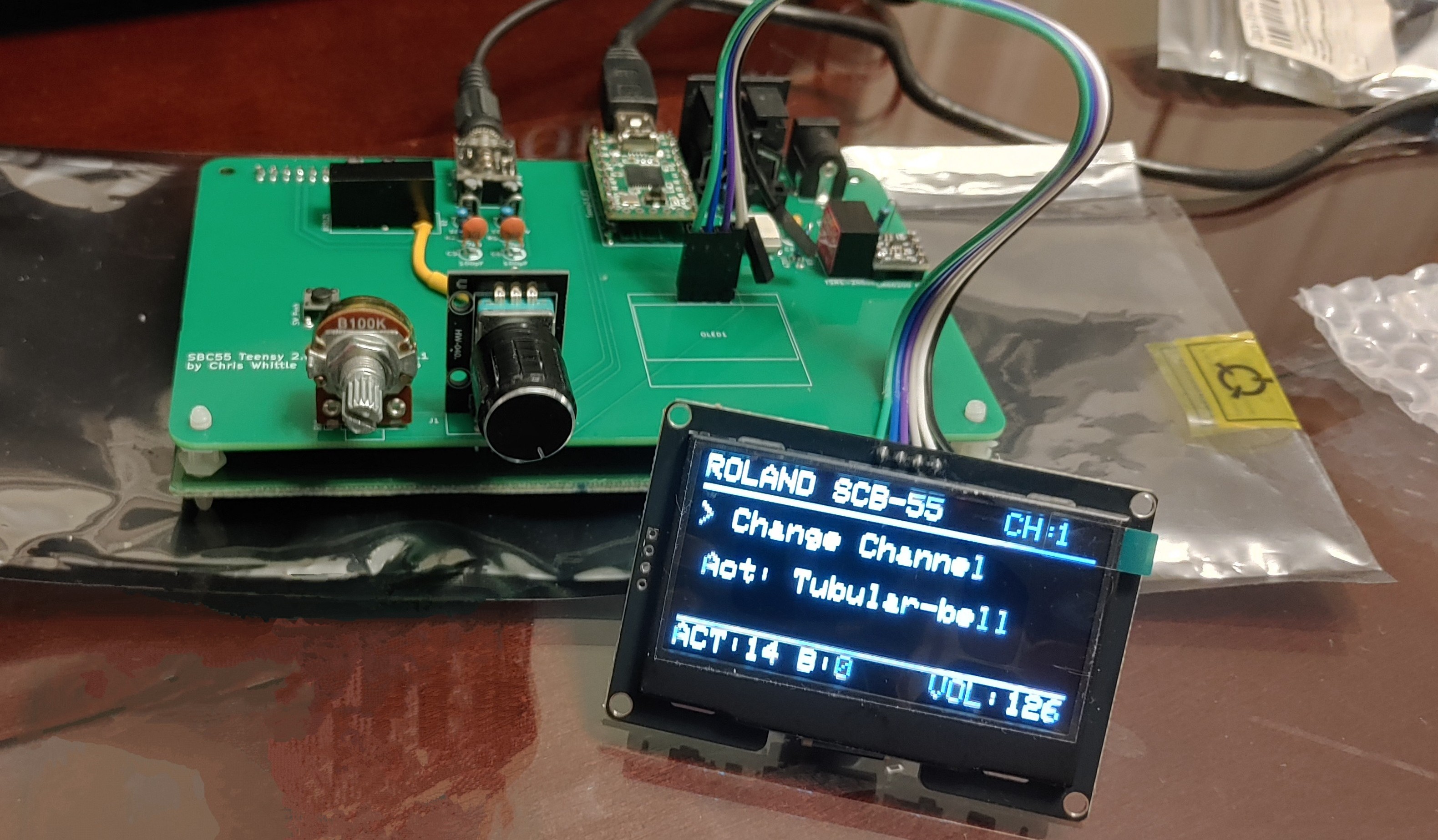
This used:
Arduino IDE 2.3.10 - IDE, Teensy2.0
KiCAD 10.0 (Along with several Footprints, please let me know if I missed credit on any), KiCad
Teensy 2.0 Footprint XenGi
FreeCAD 1.1.1 (to be used for the 3D case) - FreeCAD
along with several programs that were very helpful for debug and testing:
The excellent MIDI Player 6.5 by Zoltán Bacskó (Falcosoft) https://falcosoft.hu/
The very impressive Nuked-SC55 emulator which helped verify proper display & behaviour. Nuked-SC55
Along with Roland who created the SCB-55 GS Daughter Board that made this possible.
Other GS/GM daughter boards that use the wavetable connection should be electrically compatible, but the firmware is written for the SCB-55 and would need to be modified to control others properly. Also the board and corner holes have been sized for the SCB-55 specifically. Feel free to make your own modifications.
This project is licensed under the GNU General Public License v3 (GPLv3). See the LICENSE file in the root of this repository for the full legal text. You are free to share and adapt this code, provided all derivative works remain open-source under the same terms.
THIRD-PARTY-NOTICES.md file.Please Note:
This is Rev.1, there are some hardware errors (POT wired backwards & I should have used a WRA0512S (not A0512S)) also I'm just about out of code space in the Teensy 2.0, but it does seem to be working quite well (with the mod of adding an inline 1N5819 in front of the A0512S on the 5V line to drop +/-12V to a safe level). This diode bodge sacrifices the dual colour LED that I was planning, but it wasn't correct anyhow. (Don't get AI to 'help' design hardware without verifying results!)
This does work fully from USB only (< 350mA), or from external power with 5 pin MIDI, when connected to USB the MIDI jack is still active and either can be used (one at a time as there is no flow control). Connecting USB and external power should be safe* as I've used an ORing module to prevent voltage feedback/feedthrough, but currently you will lose USB connection with the host PC (not sure if this can be fixed, but a powered hub can be used for a weak USB port in place of the external power jack). *As long as the Teensy's Vusb is cut and wired to the board!
I plan on addressing the current hardware errors on the board and will see if I can optimize the code further as I do have some inconsistencies and some duplication in the code. I also have a few more features to add (making the POT re-assignable, and various settings saved to EEPROM, etc.) I would also like to implement the display of bank 126 (but doubt there will be enough code space for this).
Any modifications or suggestions are welcome, please remember that I don't do this professionally and I did enlist AI input / modification for some of my code, so it may not be the best implementation possible.
Once again, this works for me, but I take no liability or responsibility if any thing blows up or burns down and you assume all responsibility for creating all or parts of this project.
| Qty | Value | Footprint | References |
|---|---|---|---|
| 4 | MountingHole:MountingHole_3.2mm_M3_DIN965 | , , , | |
| 2 | 100pF | Capacitor_THT:CP_Radial_D4.0mm_P1.50mm | C3, C6 |
| 2 | 10uF 16V | Capacitor_THT:CP_Radial_D5.0mm_P2.00mm | C1, C2 |
| 2 | 10µF 16V | Capacitor_THT:CP_Radial_D5.0mm_P2.00mm | C5, C7 |
| 2 | 470Ω | Resistor_THT:R_Axial_DIN0207_L6.3mm_D2.5mm_P2.54mm_Vertical | R3, R6 |
| 2 | 47kΩ | Resistor_THT:R_Axial_DIN0207_L6.3mm_D2.5mm_P2.54mm_Vertical | R2, R5 |
| 1 | 0.1uF | Capacitor_THT:CP_Radial_D4.0mm_P1.50mm | C4 |
| 1 | 10kΩ | Resistor_THT:R_Axial_DIN0207_L6.3mm_D2.5mm_P2.54mm_Vertical | R4 |
| 1 | 10kΩ | Library:WH148 Potentiometer 3 Pin | RV1 |
| 1 | 1N4148 | Diode_THT:D_DO-35_SOD27_P7.62mm_Horizontal | D1 |
| 1 | 1N5819 | Diode_THT:D_DO-41_SOD81_P10.16mm_Horizontal | D3 |
| 1 | 220Ω | Resistor_THT:R_Axial_DIN0207_L6.3mm_D2.5mm_P2.54mm_Vertical | R1 |
| 1 | 2x13 | Connector_PinHeader_2.54mm:PinHeader_2x13_P2.54mm_Vertical | J2 |
| 1 | AudioJack | Connector_Audio:Jack_3.5mm_Ledino_KB3SPRS_Horizontal | J4 |
| 1 | H11L1 | Package_DIP:DIP-6_W7.62mm | U3 |
| 1 | IA0512S | Converter_DCDC:Converter_DCDC_XP_POWER-IAxxxxS_THT | U2 |
| 1 | Jack-DC | Connector_BarrelJack:BarrelJack_Horizontal | J5 |
| 1 | LED_Dual_CommonAnode | Library:LED_3Pin_2.54mm | D2 |
| 1 | LM66200 Mod | Package_DIP:DIP-8_W7.62mm | U4 |
| 1 | MIDI | Library:DIN5_MIDI | J3 |
| 1 | Rotary Encoder | Library:Rotary Encoder Board with Switch | J1 |
| 1 | SSD1306 | Library:128x64OLED | OLED1 |
| 1 | SW_Push | Button_Switch_THT:SW_PUSH_6mm | SW1 |
| 1 | TSR1-2450E | Converter_DCDC:Converter_DCDC_TRACO_TSR1-xxxxE_THT | U5 |
| 1 | Teensy2.0_(C) | Library:Teensy2.0 | U1 |
| 1 | Vusb | TestPoint:TestPoint_THTPad_2.0x2.0mm_Drill1.0mm | TP1 |

Ayan-nova/Design-of-a-Raspberry-PICO-Iot-Device-on-4-Layer-PCB-Design-With-Sensor-And-More
Design a Raspberry Pi Pico W-based Industrial IoT Gateway and Edge Controller using Kicad software.

baloghr/usonic
KiCad 9 project gp2026 (hardware revision 1.01): schematic, PCB, custom footprints (Library.pretty) and 3D models (packages3D).

ismailEngineer/omniwheel-robot
a small protoype to educate the control system of 3 OmniWheel Robot


Unimakers/CDR-2027
Ce repo est un site de documentation réalisé par l'équipe des première et deusième années pré-ingénieur de l'école Unilasalle-Amiens, membre de l'association de robotique Unimaker, dans le cadre de leur participation à…


It measures 137 × 89 mm and has 2 copper layers, 1.6 mm thick.
34 parts, built around the IA0512S, TSR 1-2450E and H11L1. The full list of its parts is on this page, with links to each part's symbol and footprint where PCBKit's library has them.
From the DVDPlayer/SCB55Teensy2cw repository on GitHub, at the commit this page was made from: the board is hardware/pcb/SCB55_Teensy2.kicad_pcb and its schematic hardware/pcb/SCB55_Teensy2.kicad_sch. PCBKit opens the board in the browser, with nothing to install.
Its repository publishes it under the GPL-3.0 licence: you may reuse it on that licence's terms (keep the author's notice, and for a copyleft licence share your changes alike).