2 layers48.8 × 50.4 mm
 DDeGonge/MiniBot47
Super cheap super tiny bots for....playing chess...
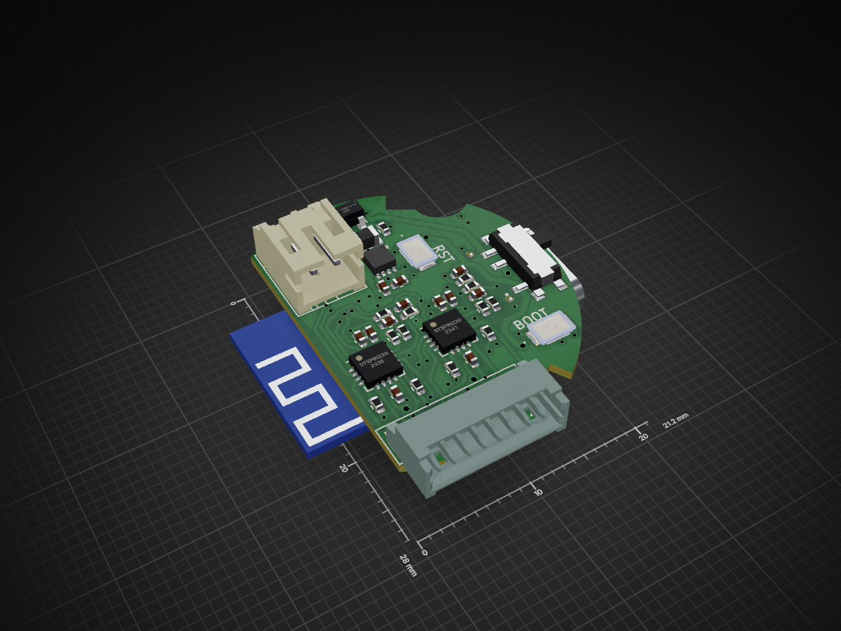
MiniBot is an open-source printed circuit board by DDeGonge, from the DDeGonge/MiniBot repository on GitHub, published under the MIT licence. It is a 4-layer board of 21 × 27.9 mm with 60 parts on 73 nets, routed with 675 tracks and 82 vias.
It is built around the ESP32-C3-MINI-1-H4X, STSPIN220 and MIC23050-SYML-TR, with the MMC5633NJL, EASV2010RWA0 and GSB1C41110SSHR among its other parts. Its parts include 23 resistors, 19 capacitors, 6 ICs, 3 connectors and 3 switches. It belongs with the ESP32 and RISC-V boards of this library.


A swarm robotics platform built around autonomous chess. The system runs 34 small differential-drive robots across an 8x8 board, each independently localized and coordinated by a central Python application running on a Raspberry Pi.
The design is general-purpose — chess is the primary use case, but the platform works for any scenario requiring coordinated movement of many small autonomous robots in a bounded space.
Per-bot hardware cost is approximately $4 excluding PCB.
The system has three layers:
Coordinator is a Python/PyQt6 application running on a Raspberry Pi. It holds board state, runs path planning, drives the GUI, and sends motion commands to the Server over USB serial.
Server is an ESP32 on the motherboard. It acts as a wireless gateway: it receives CSV commands from the Coordinator over USB serial, translates them to binary ESP-NOW messages, and broadcasts them to the bots. It also drives the electromagnets used for localization and collects ACK/NACK responses back up to the Coordinator.
MiniBots are the robots themselves. Each runs an ESP32-C3 with five concurrent FreeRTOS tasks handling motion control, wireless communication, position estimation, and battery management entirely onboard.
| Component | Details |
|---|---|
| MCU | ESP32-C3 (RISC-V, 2.4 GHz WiFi) |
| Motors | 2x PMO8-2 miniature stepper motors |
| Motor drivers | STSPIN220 |
| Magnetometer | MMC5633NJL (I2C) |
| Power | ~170 mAh LiPo |
| Chassis | Fully 3D printed; 2x M2x5mm bolts, 2x 7mm ID o-rings for tires |
| PCB | Custom 4-layer; fits in the base of the chassis |
| Component | Details |
|---|---|
| MCU | ESP32-C3 (RISC-V, 2.4 GHz WiFi) |
| Electromagnets | Multiple, positioned at fixed known coordinates on the board |
| Interface | USB serial to Raspberry Pi |
| WiFi | Soft AP; bots connect on a dedicated channel |
The electromagnets fire in a timed sequence that the MiniBots detect with their onboard magnetometers. This is the primary localization mechanism.
flowchart TD
    subgraph Coordinator["Coordinator (Raspberry Pi)"]
        GUI["GUI / Path Planner"]
        SH["SerialHandler\n(QThread)"]
        GUI -->|MoveCommand list| SH
    end

    subgraph Server["Server (Motherboard ESP32)"]
        ST["SerialTask"]
        CT["CommunicatorTask"]
        ET["ElectromagnetTask"]
        ST -->|CommandMessage| CT
        CT -->|GUIStatus| ST
    end

    subgraph Bots["MiniBot #1 ... #34 (ESP32-C3)"]
        COMM["EspNowCommunicator"]
        KIN["KinematicsController"]
        PE["PositionEstimator"]
        COMM -->|MotionCommand| KIN
        COMM -->|sync time| PE
    end

SH -->|"Serial CSV Commands"| STAll messages are prefixed with >. The Server parses these and forwards the
appropriate ESP-NOW message to the targeted bot(s).
| Type | Direction | Format |
|---|---|---|
| 0 | Host to ESP32 | >0,{id},{mode},{duty1},{duty2} -- motor test |
| 1 | Host to ESP32 | >1,{id},{x},{y},{theta_rad},{duration_ms} -- position command |
| 2 | Host to ESP32 | >2,{id} -- position request |
| 3 | ESP32 to Host | >3,{id},{x},{y},{theta_rad},{timestamp_ms},{battery_v} -- ACK |
| 4 | ESP32 to Host | >4,{id},{err_type},{timestamp_ms} -- NACK |
| 5 | Host to ESP32 | >5,{id} -- mag field request |
| 6 | ESP32 to Host | >6,{id},{bx},{by},{bz},{timestamp_ms} -- mag field response |
| 7 | Host to ESP32 | >7 -- sync broadcast |
| 254 | Host to ESP32 | >254,{0 or 1} -- electromagnet enable/disable |
| 255 | Both | >255 -- ping/pong |
Theta is transmitted in radians on the wire. The Coordinator converts internally; all application-level code uses degrees.
Binary packed structs defined in ESPNowMessages.h (Server) and
messages_espnow.h (MiniBot). Key message types: PositionCommand,
MotTestCommand, PositionRequest, PosSync, AckMessage, NackMessage,
MagneticFieldRequest, MagneticFieldResponse.
Before a localization measurement can be taken, every MiniBot needs to know precisely when the electromagnet frame will begin so it can timestamp its magnetometer samples against a common reference.
Initiating a sync is triggered by the Coordinator sending a >7 sync command.
The Server's CommunicatorTask handles it as follows:
PosSyncCommand is broadcast to all bots. The message includes a timeout
indicating how long the bots should stay awake listening for the frame.PosSync pulses. Each
carries a next_frame_us field indicating how many microseconds until the
electromagnet frame starts.ElectromagnetTask fires the frame immediately after the burst completes.On each MiniBot, when PosSyncCommand is received, EspNowCommunicator sets
a deadline and raises waiting_for_pos_sync. The ESP-NOW receive callback captures
a high-resolution timestamp the instant each PosSync pulse arrives, before any
further processing. The task keeps only the earliest-arriving pulse from the burst —
minimum latency gives the best timing accuracy. The estimated frame start is
receive_time + next_frame_us from that best pulse.
Once the deadline passes, the bot calls PositionEstimator_SetSyncTime() with the
estimated frame-start, then sends an ACK with a small random delay to spread
simultaneous responses from many bots. If no pulse arrived in time, it sends
ERR_SYNC_TIMEOUT.
Radio duty cycling is tied to sync health. After a successful sync, each bot enables duty cycling to save power. If sync becomes stale, the radio reverts to always-on so the Server can reach the bot to re-establish sync.
The Server fires each electromagnet in sequence as part of a repeating frame. Each slot has a brief forward and reverse pulse to produce a detectable field, with a known timing offset between slots.
On each MiniBot, PositionEstimator_SensorTask reads the magnetometer
continuously. Once a valid sync time is set, it timestamps each sample relative to
the frame start and assigns samples to their electromagnet slot by timing alone.
Once a complete frame is collected, PositionEstimator_CalcTask performs
trilateration using the field strength readings from the closest electromagnets and
their known board positions. This yields an (x, y, orientation) estimate with a
confidence score, which is used to weight a low-pass filter before the result is
committed to the robot's true pose via robot.setTruePose().
Current board designs are in pcbs/:
pcbs/MiniBot_MainBoard/ -- MiniBot PCB (ESP32-C3, stepper drivers, magnetometer, LiPo charger)pcbs/Server_Motherboard/ -- Motherboard (ESP32-C3, electromagnet drivers, connectors)Gerber files are in the GERBERS/ subdirectory of each board folder.
CAD (OnShape): https://cad.onshape.com/documents/4f8eaef75458146767928ab5/w/f159d6d65b9091531e1ead34/e/13b51722310f27710438c727
Each firmware project has its own README with task breakdowns, key objects, and build instructions.
firmware/MiniBot_Coordinator/ -- Python/PyQt6 host applicationfirmware/MiniBot_Server/ -- ESP32 motherboard firmware (PlatformIO)firmware/MiniBot_StepperClient/ -- ESP32-C3 per-bot firmware (PlatformIO)| Qty | Value | Footprint | References |
|---|---|---|---|
| 10 | 0.1uF | Capacitor_SMD:C_0402_1005Metric | C2, C4, C5, C6, C9, C15, C16, C19, C20, C23 |
| 6 | 10k | Resistor_SMD:R_0402_1005Metric | R3, R4, R5, R6, R9, R12 |
| 4 | 1 | Resistor_SMD:R_0402_1005Metric | R18, R19, R22, R23 |
| 4 | 5.1k | Resistor_SMD:R_0402_1005Metric | R1, R2, R14, R15 |
| 3 | 1k | Resistor_SMD:R_0402_1005Metric | R13, R16, R20 |
| 3 | 390k | Resistor_SMD:R_0402_1005Metric | R7, R10, R11 |
| 3 | 4.7uF | Capacitor_SMD:C_0402_1005Metric | C1, C8, C10 |
| 2 | 10uF | Capacitor_SMD:C_0402_1005Metric | C17, C21 |
| 2 | 22nF | Capacitor_SMD:C_0402_1005Metric | C18, C22 |
| 2 | 47k | Resistor_SMD:R_0402_1005Metric | R24, R25 |
| 2 | EVP-AWBD4A | minibot:EVPAWBD4A | S2, S3 |
| 2 | Jumper_3_Bridged12 | Jumper:SolderJumper-3_P1.3mm_Bridged12_RoundedPad1.0x1.5mm | JP1, JP2 |
| 2 | STSPIN220 | Package_DFN_QFN:VQFN-16-1EP_3x3mm_P0.5mm_EP1.8x1.8mm | U4, U5 |
| 2 | TestPoint | TestPoint:TestPoint_Pad_D1.0mm | TP1, TP2 |
| 1 | 12.4k | Resistor_SMD:R_0402_1005Metric | R8 |
| 1 | 1uF | Capacitor_SMD:C_0402_1005Metric | C3 |
| 1 | 560pF | Capacitor_SMD:C_0402_1005Metric | C7 |
| 1 | Conn_01x02 | Connector_JST:JST_PH_S2B-PH-K_1x02_P2.00mm_Horizontal | J2 |
| 1 | Conn_01x08 | Connector_Molex:Molex_PicoBlade_53047-0810_1x08_P1.25mm_Vertical | J1 |
| 1 | EASV2010RWA0 | minibot:EASV2010RWA0 | LED1 |
| 1 | ESP32-C3-MINI-1-H4X | minibot:ESP32C3MINI1H4X | U1 |
| 1 | GSB1C41110SSHR | minibot:GSB1C41110SSHR | J3 |
| 1 | L | Inductor_SMD:L_0805_2012Metric | L1 |
| 1 | MCP73832-2-OT | Package_TO_SOT_SMD:SOT-23-5 | U3 |
| 1 | MIC23050-SYML-TR | SamacSys_Parts:SON50P200X200X90-9N-D | IC2 |
| 1 | MMC5633NJL | minibot:BGA4C40P2X2_85X85X60 | IC1 |
| 1 | PCM12SMTR | minibot:PCM12SMTR | S1 |


ajwock/quadcopter
Quadcopter designed and programmed thoroughly from scratch

thebenedict/seattletransit-hardware
Schematic and PCB for a circuit board map of Seattle area public transit.

nikolaus018/garageDoor-pro
ESP32-C3 + GPS board that opens the garage door when you leave and arrive: firmware, KiCad PCB and perfboard build

zeugmaster/nucula-board
Nucula Board: an ESP32-C3 hardware prototype with USB-C, PN7160 NFC, OLED and detachable keyboard. KiCad sources and manufacturing files.


thousandflame1000/aetherpose
2026-10-18。已選方向:沿用 Arduino Nano 33 BLE 原版 ABX00030/帶針 ABX00034(LSM9DS1),製作供電與固定底板;六個穿戴位置各用一套。


Pioneer-Rocketry/Flight-Computer
Pioneer Rocketry’s latest generation flight computer for high power, STM32-based avionics system designed for experimental high-power rockets.
It measures 21 × 27.9 mm and has 4 copper layers, 0.8 mm thick.
60 parts, built around the ESP32-C3-MINI-1-H4X, STSPIN220, MIC23050-SYML-TR and MMC5633NJL. The full list of its parts is on this page, with links to each part's symbol and footprint where PCBKit's library has them.
From the DDeGonge/MiniBot repository on GitHub, at the commit this page was made from: the board is pcbs/MiniBot_MainBoard/MiniBot.kicad_pcb and its schematic pcbs/Charge_Case/ChargePort.kicad_sch. PCBKit opens the board in the browser, with nothing to install.
Its repository publishes it under the MIT licence: you may reuse it on that licence's terms (keep the author's notice, and for a copyleft licence share your changes alike).