
2 layers52 × 63 mm
TOP
Chrismettal/PedalDev
Complete audio effect stompbox ecosystem and collection of designs
100 parts11

 Chrismettal/PedalDev11
Complete audio effect stompbox ecosystem and collection of designs
Proto Simple is an open-source printed circuit board by Chrismettal, from the Chrismettal/PedalDev repository on GitHub. It is a 2-layer board of 52 × 63 mm with 383 parts on 13 nets, routed with 66 tracks and 0 vias.
It belongs with the audio and music boards of this library.


This is a convenient system for quickly creating stompboxes, as well as a collection of designs made with this system.
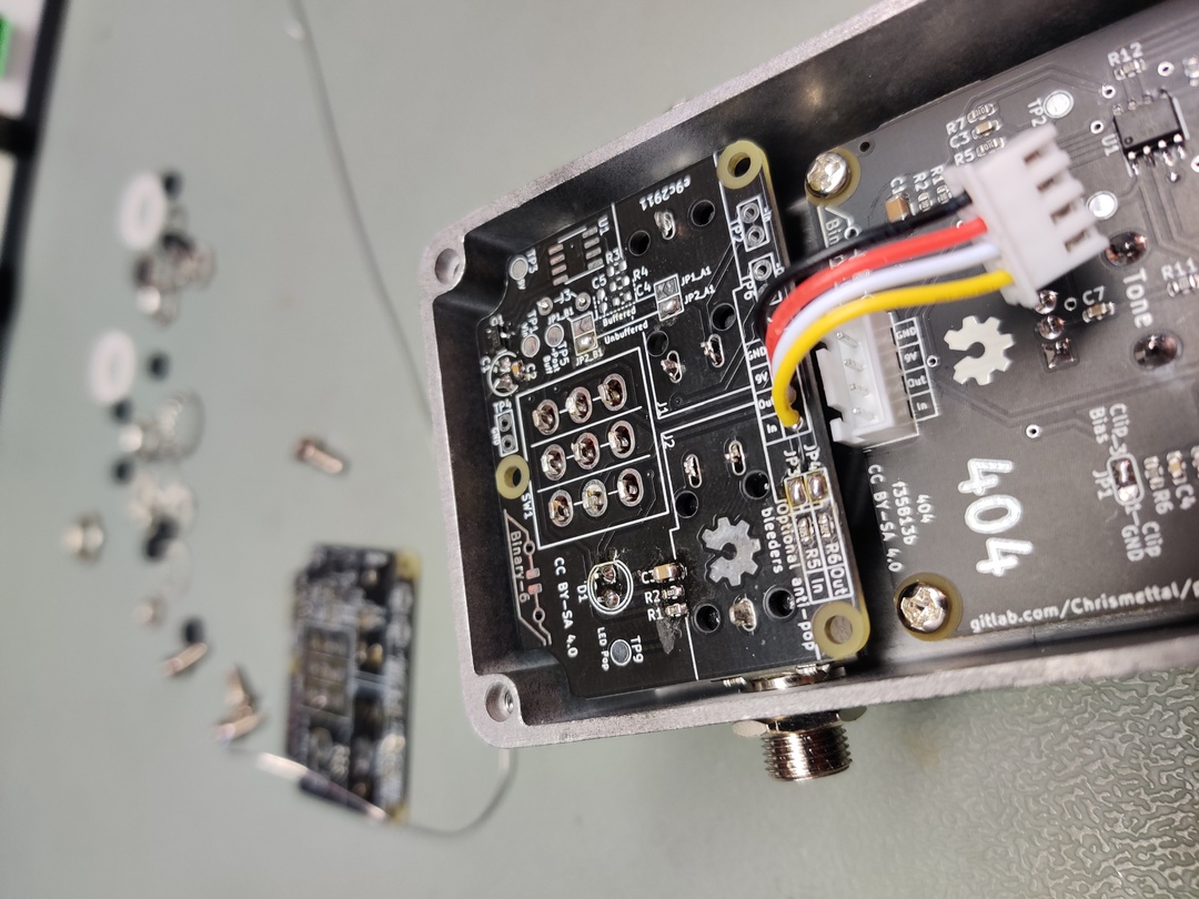
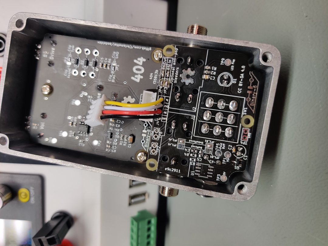
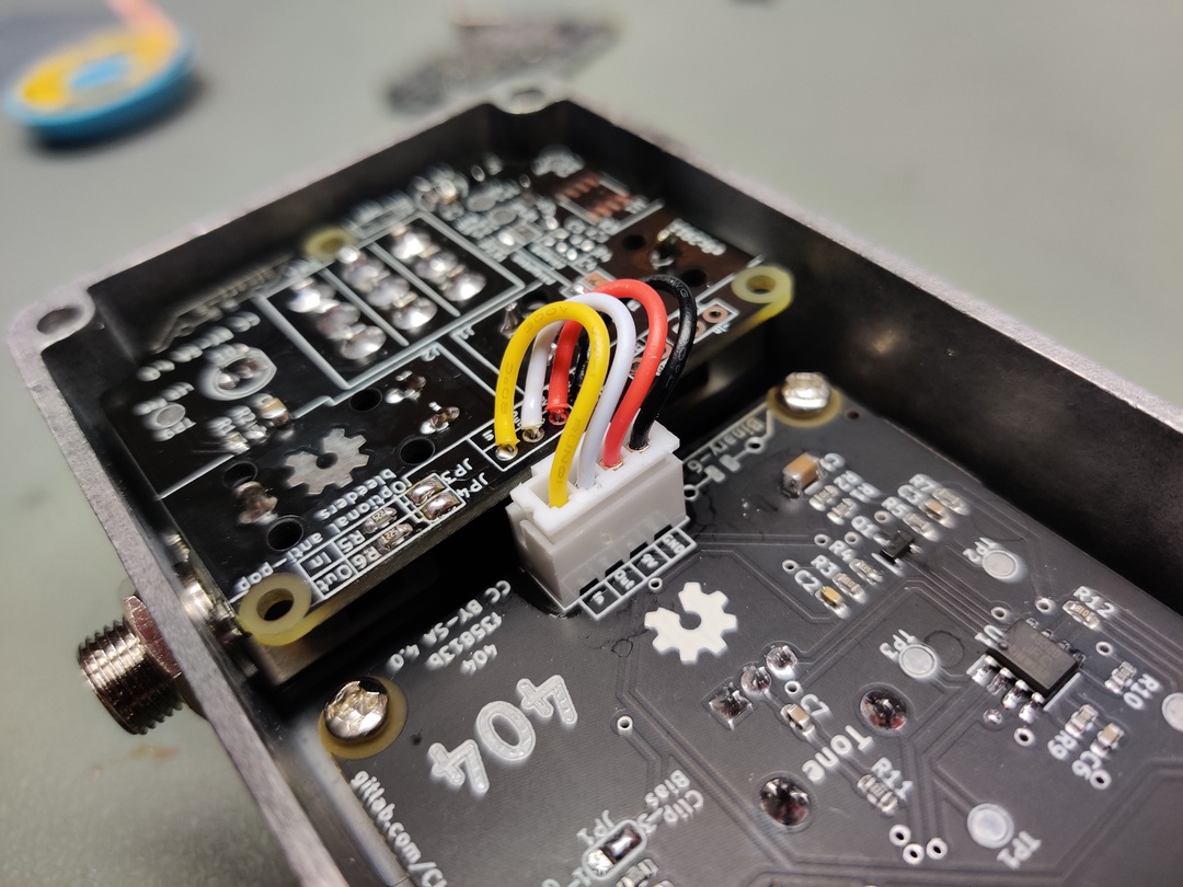
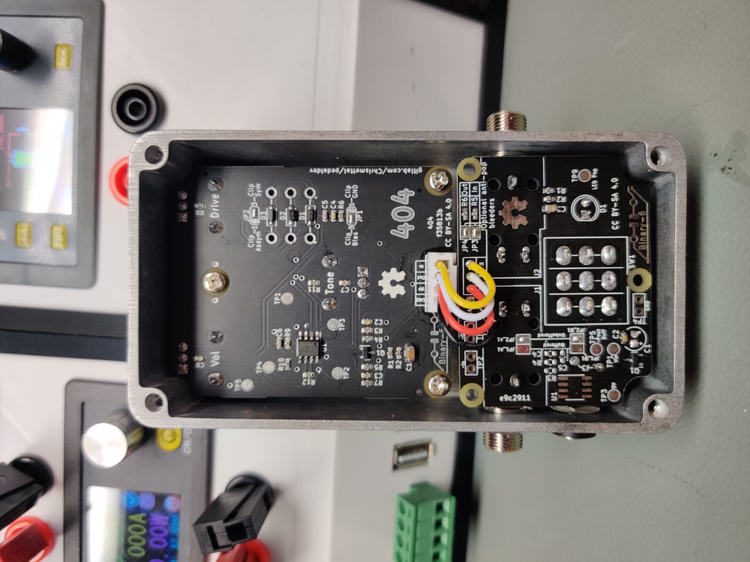
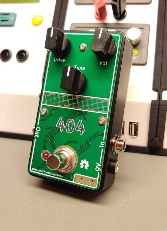
The design is split into two boards, a lower and an upper one. The lower PCB handles all of the I/O, switching, and power stuff, while the upper one focuses on the individual effect. The two boards plug together and fit neatly inside a commonly used Hammond 1590B. For each finished design there is also a PCB frontpanel so I don't have to deal with any actual design work and can just hide my designs behind technical looking stuff. The actual boards take full advantage of modern SMD components for optimal space usage.
All designs build up from the same template to allow rapid creation of new designs as well as saving time on recurring steps. There are even various protoboard variants of the upper PCB fitting the same template, to make boutique one-off designs more convenient and robust. For every design you will find the full KiCAD project including schematic and production files like BOM, Gerbers and PCBA place files in their respective project folders. (/pcb/*)
For easy mechanical manufacturing a 3D printable drilling template is provided. There is also a 3D printable design of the full stompbox similar to the 1590B with all ports "predrilled". A plastic case is not super recommended though and should only be used for quick testing. Conductive spray paint as shielding on the inside is also recommended when using the 3D printed case. (/3d/*)
Parts marked with ":construction:" are work in progress and not fully verified yet.
Individual boards, predrilled cases as well as kits will be stocked at Tindie!

If you like my work please consider supporting my caffeine addiction!
While there aren't many specific designs right now, they will be created faster now that the system is proven working. There is a wide range of devices in the works, from high gain distortions over reverbs to new, experimental stuff.
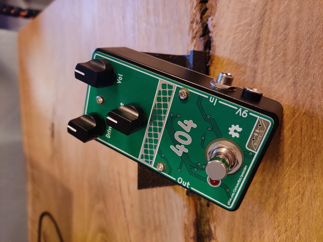
Based on the popular Tubescreamer this is obviously the first design to be done in this system.
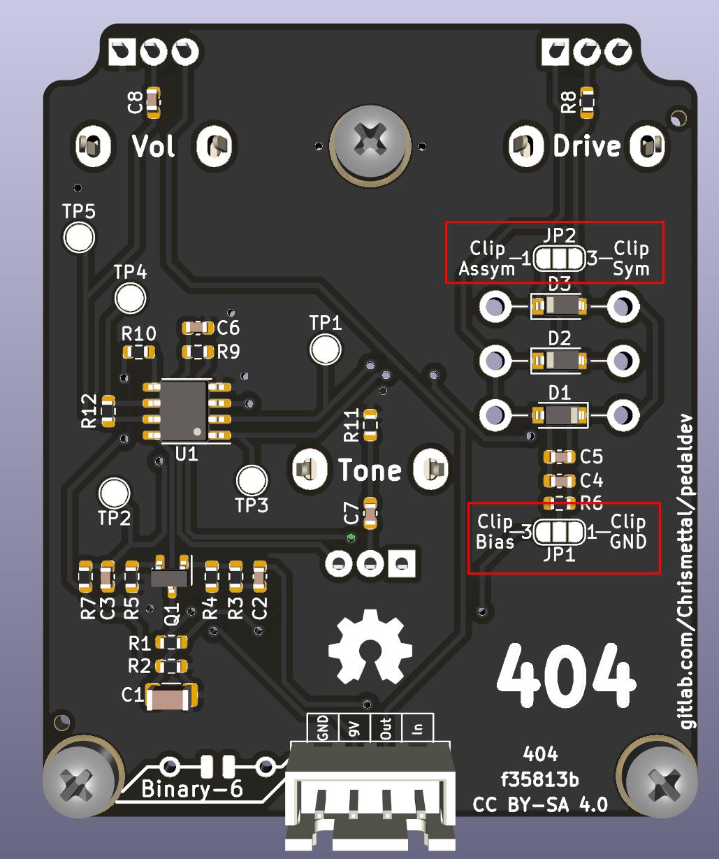
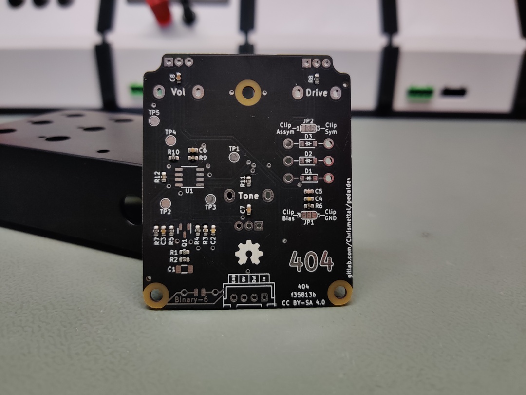
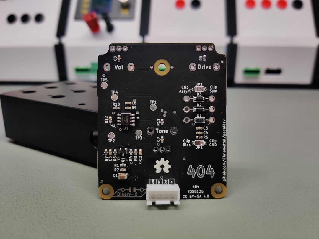
Nothing crazy here, only D1-3 feature a dual footprint to put in your favourite clipping diodes.
There are two jumpers that need to be set when building this board. JP1 does not really do anything with the sound but chooses a filter to be sent to ground or to bias voltage as some schematics have it either way. JP2 however allows choosing betweeen symmetrical or assymetrical clipping.
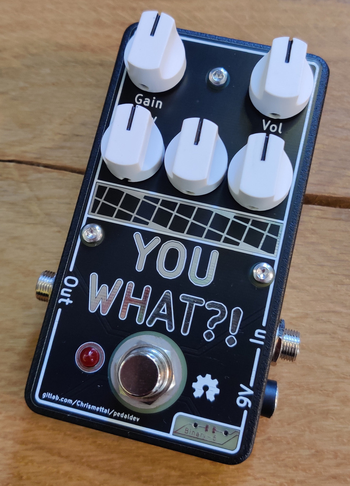
Very cheap in parts but incredibly tight high gain distortion with lots of attack.
:construction: :construction: :construction: Work in progress :construction: :construction: :construction:
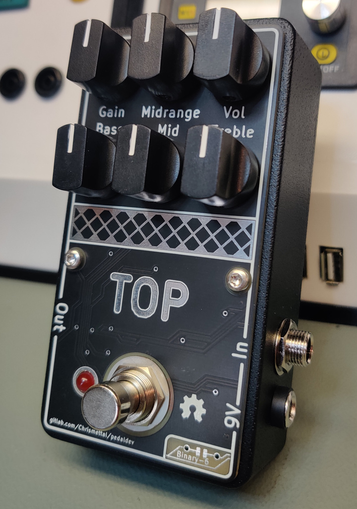
Based on schematic by Saruman found here.
First PCB version f35813b was broken is currently being debugged. 4 Pins on TL074 were swapped, ICL7660 does not work when BOOST mode is set (But ICL7660S does..), and input stage sounds super starved, more like a bassy fuzz than a distortion. Simulation seems to confirm this so confidence in schematic is low. Currently getting hold of an original Dominator for schematic comparison.
Two jumpers on board revision f35813b are for debugging the power stage around the 7660 but will probably be removed or clarified on the fixed revision
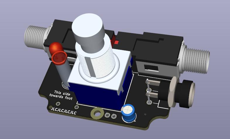
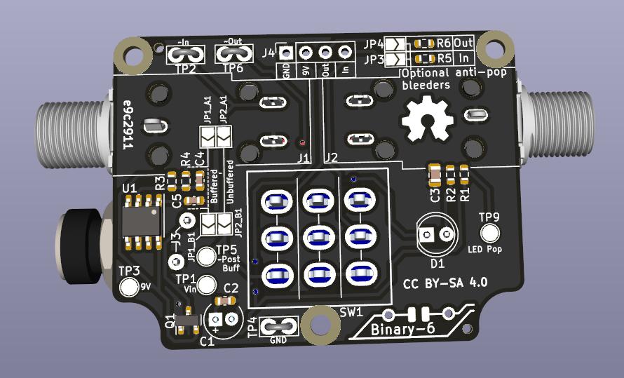
The lower PCB consists of the bypass footswitch with a status LED, input and output jacks as well as power input, filtering and FET based reverse polarity protection.
The Input/Output jacks are called PJ-602B. These are not available via LCSC sadly, but can be found all over Aliexpress.
Additionally an optional TL07X based buffer can be enabled via two jumpers. This was only added because the PCB had enough room for it and it can save room on the pedalboard instead of adding a separate buffer box. The buffer parts do NOT NEED to be populated if you intend never to use them. Either JP1_A1 and JP1_B1 or JP2_A1 and JP2_B1 need to be set for signal to be passed through.
The LED is driven through a simple "anti pop" filter and two optional anti-pop bleeders can be enabled via JP3 and JP4 to bleed any input/output caps on the connected upper board if neccessary.
Test hooks and pads are sprinkled on interesting signals for effect development and debugging.
:bulb: Hint:
While this system is intended to be used with one lower PCB and one upper PCB fitting together, it might be convenient to just use the lower PCB even if you do not intend to use an actual effect from this system. Doing so greatly reduces the amount of free form wiring and frees up some space on your actual effect PCB.
:construction: :construction: :construction: Work in progress :construction: :construction: :construction:
Same as Lower, but instead of a true bypass 3PDT Switch it features a microcontroller to turn your effect on and off either in momentary or latching mode. To show the mode it's currently on, it uses a bicolor LED.
On initial bootup, the device will be in latching mode. Pressing the button will toggle the effect on and off. The :construction: colored LED will be on as long as the effect is on in toggle mode. Holding the button down for 9 seconds, both LEDs will start blinking, signaling that a mode change is imminent. Holding the button for one more second, the device will switch into momentary mode. In momentary mode, the effect will only be on while the button is held. While the effect is on, a :construction: colored LED will be on in momentary mode. Switching back to toggle mode works the same way, by holding down the button long enough.
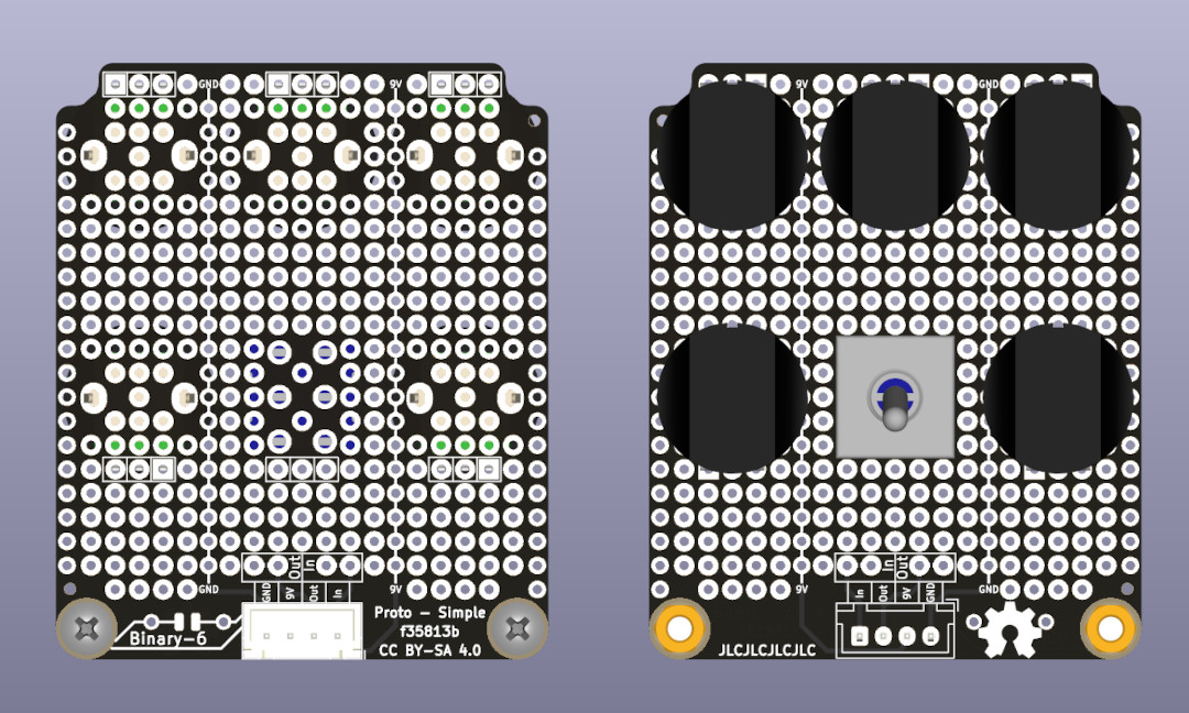
This is a simple protoboard to use as an "upper" board, allowing for up to 6 pots, or 5 pots with one DPDT print switch. It features 9V and GND power rails straight through the design to allow for easy power distribution
While it does not allow for the density of SMD components it can certainly fit a lot of designs.
I would love to merge your designs using this system into this repo!
To design your own effect PCB, create a copy of the UpperRaw KiCAD project for the actual effect, and FrontRaw for a PCB frontpanel design. UpperRaw includes a collection of frequently used parts in the schematic, set up with LCSC part numbers etc. It would be great if you add LCSC part numbers to all parts used in your design as well. After merging I will recreate the production files to the same parameters as the already created designs so don't worry about that.
As the system tries to use the little space in the 1590B as efficient as possible, the actual build can be quite tight. There is a set order of steps that should be taken to make the build as quick and easy as possible.
The whole system is designed so the PCBs can be ordered from JLCPCB mostly populated, so only very little hand soldering is involved. If you order the boards finished you will mostly have to solder only the through hole components, but for some rare components that JLCPCB doesn't populate, it might be neccessary to solder some SMD components manually. SMD components go down to 0603 for passives, and SOIC-* / SOT-* for actives, which is still hand solderable without too much trouble. A hot air solder station is highly recommended though.
If you have access to a 3D printer (or to my Tindie Shop), there is a printable drill guide available. Otherwise, there will be a techdraw sheet with all the dimensions. At the shop you will also find predrilled, black cases directly manufactured by Hammond.
All models are compatible with the same drill layout. Holes not required for a specific board will be hidden by the front plate, so the fully stacked 6 controls variant works for every model.
Put the case in the drill guide and use a center punch to mark out all the holes to be drilled
Pre-drill all marked holes with a 3mm drill bit (The smallest size used on the device)
Drill out all the holes to the sizes marked on the drill guide. Note that the holes are all 0.5mm - 1mm larger than they need to be to make alignment of the frontpanel easier
If you want to paint the case, this would be the step to do it. I clean the case with rubbing alcohol, prime and paint, while only focusing on the sides of the case as I will hide the top underneath the frontpanels.
JP1_A1 and JP1_B1 or JP2_A1 and JP2_B1 need to be set for signal to be passed through.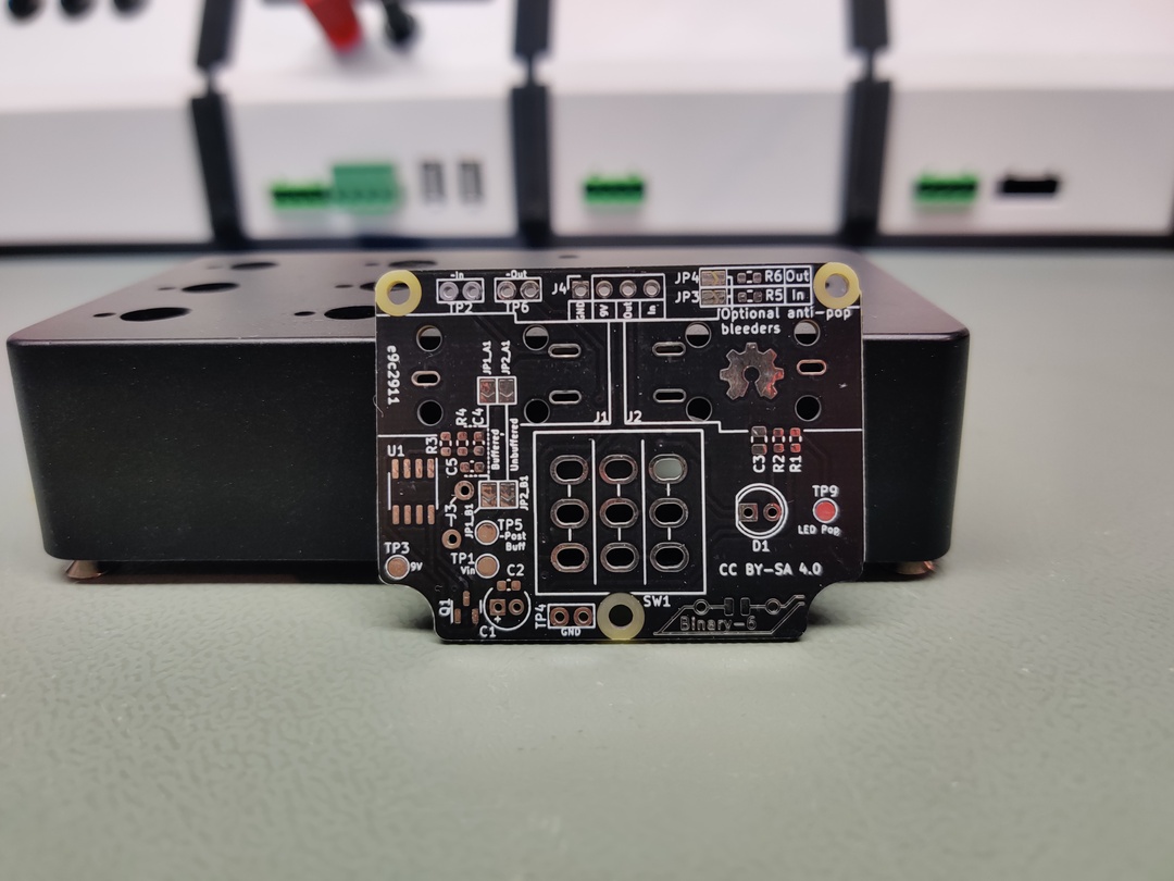
Buffered - Unbuffered jumpers for the Lower PCB. Note the individual boards documentation.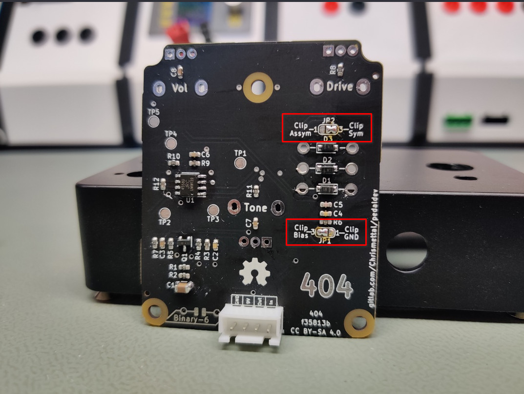
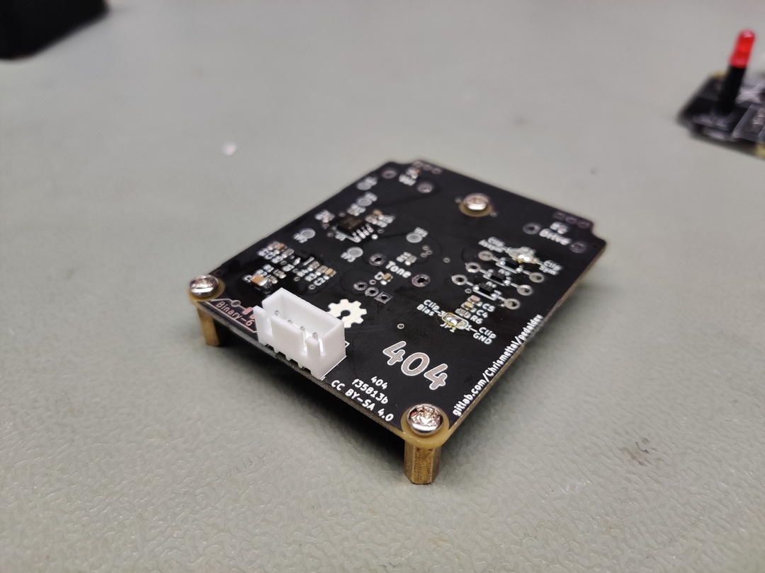
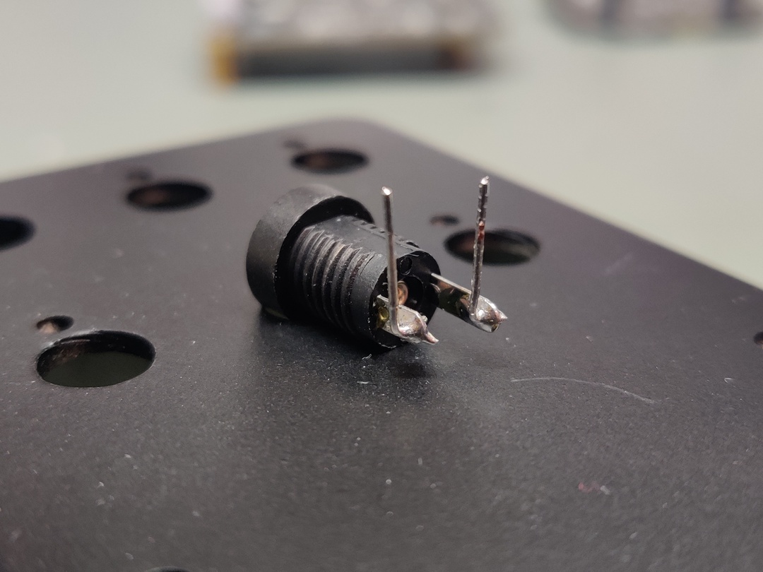
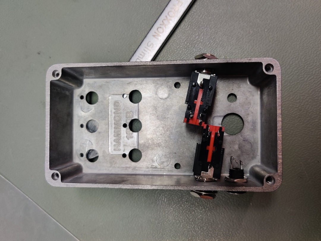
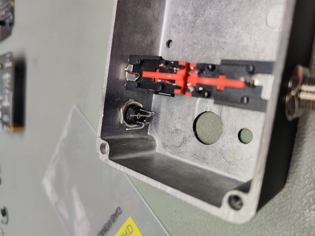
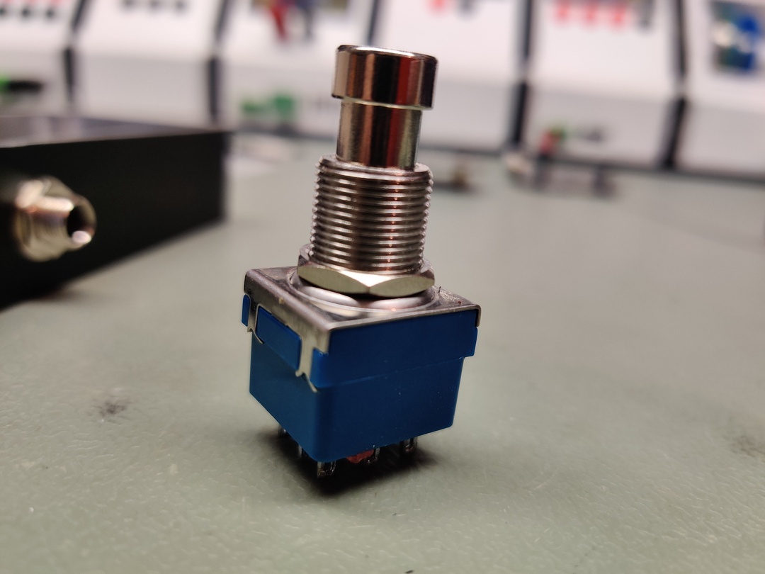
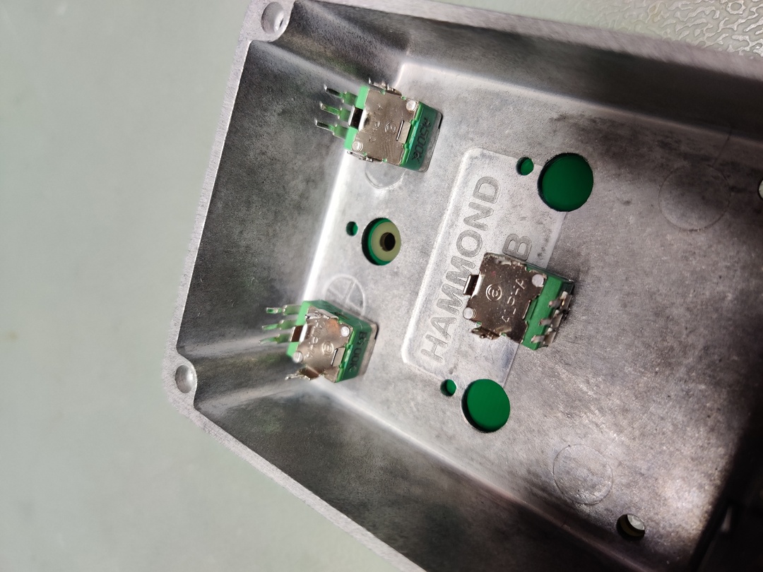
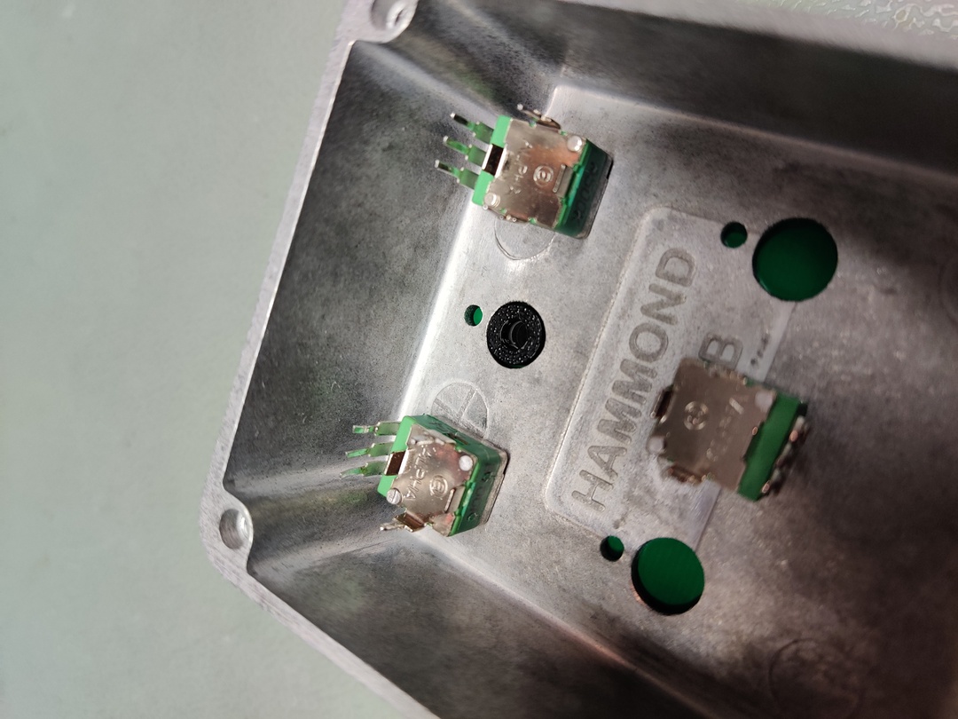
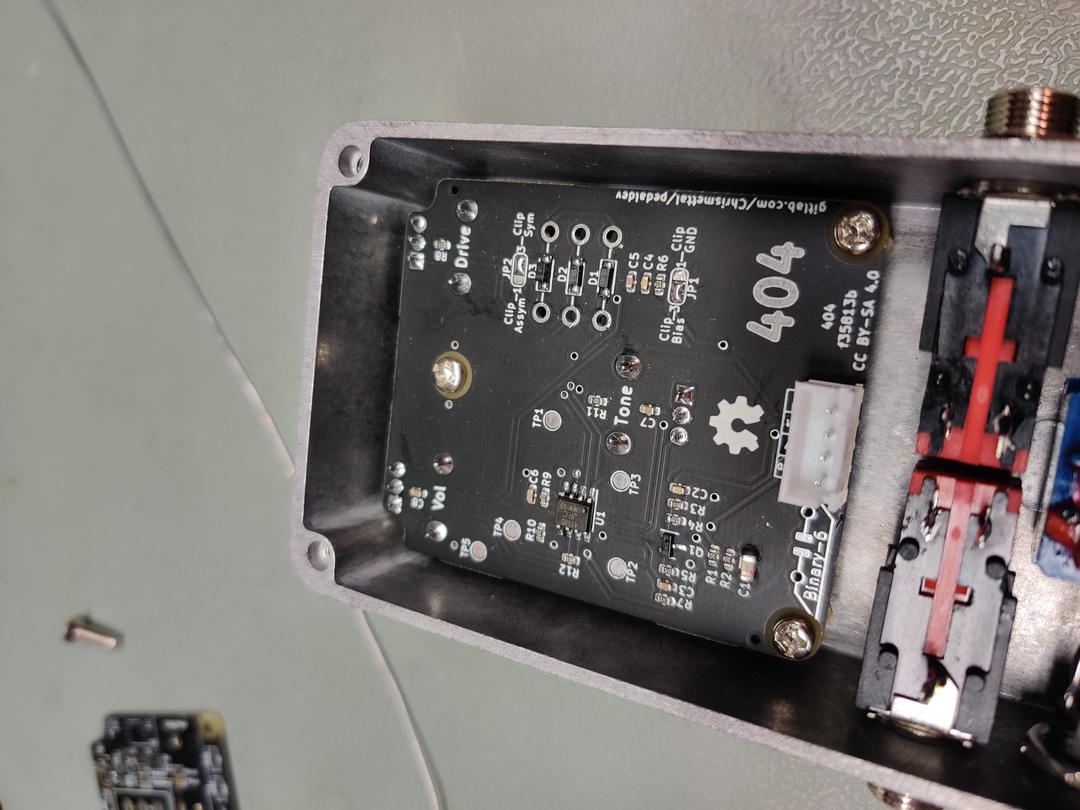
The following 3D models were used for the simulation renders in KiCAD and FreeCAD. Please check their respective licenses if you intend to reuse them.
Any models that are not mentioned here were created by me for this project and are subject to the same license as the whole repo.
| File | Link |
|---|---|
| Hammond 1590B | https://www.hammfg.com/part/1590B |
| PJ-602B Audio jacks | https://github.com/afedorov3/3DModels |
| Footswitch_3PDT | https://grabcad.com/library/3pdt-switch-1 |
| 9mm potentiometers | https://grabcad.com/library/alpha-rd901f-40-15r1-1 |
| DC barrel jack | https://grabcad.com/library/5-5mm-panel-mount-dc-jack-1 |
| LED 5mm | https://grabcad.com/library/led-5mm-1#! |
If you like my work please consider supporting my caffeine addiction!

This work is licensed under a Creative Commons Attribution-ShareAlike 4.0 International License.
| Qty | Value | Footprint | References |
|---|---|---|---|
| 40 | Conn_01x01 | MeineBib:Protopin_Small | J10, J11, J12, J13, J14, J15, J16, J17, J18, J19, J20, J21, J22, J23, J24, J25 +24 |
| 5 | 100K Lin | MeineBib:Potentiometer_Alpha_RD901F-40-00D_Single_Vertical | RV100, RV101, RV102, RV200, RV200 |
| 4 | Conn_01x01 | MeineBib:Protopin | J2, J3, J4, J5 |
| 2 | Mounting_Hole_M3 | MeineBib:EigenesMountingHole_3.2mm_M3_Small | MK2, MK2 |
| 1 | Conn_01x04 | Connector_JST:JST_XH_B4B-XH-A_1x04_P2.50mm_Vertical | J1 |
| 1 | Symbol_Binary6 | MeineBib:Binary_6_v0.1_tiny_silk | H7 |
The 53 most common of 383 parts.
Chrismettal/PedalDev
Complete audio effect stompbox ecosystem and collection of designs

Chrismettal/PedalDev
Complete audio effect stompbox ecosystem and collection of designs

Chrismettal/PedalDev
Complete audio effect stompbox ecosystem and collection of designs

Chrismettal/PedalDev
Complete audio effect stompbox ecosystem and collection of designs

Chrismettal/PedalDev
Complete audio effect stompbox ecosystem and collection of designs


Hy-5/VesselV3
Custom "Vessel" Keyboard - PCB + 3D Case Model + Firmware + Keycaps vector


CRImier/MyKiCad
My KiCad boards. Can't be bothered uploading individually anymore, so here you go.


sbarisic/MagMouse
Open source hall-effect based mouse - no mechanical contacts - no failure points
It measures 52 × 63 mm and has 2 copper layers, 1.6 mm thick.
383 parts. The full list of its parts is on this page, with links to each part's symbol and footprint where PCBKit's library has them.
From the Chrismettal/PedalDev repository on GitHub, at the commit this page was made from: the board is pcb/Proto-Simple/Proto-Simple.kicad_pcb and its schematic pcb/404/404.kicad_sch. PCBKit opens the board in the browser, with nothing to install.
Its repository states no licence, so its author keeps all rights: ask Chrismettal before reusing the design.