

2 layers50 × 100 mm
Corrector de postura
agustin-arg/Posture
Dispositivo electrónico de corrección de postura corporal
23 parts5

 Chihhao/ESP32-MAX7219-LED-Matrix-Display1
這是一個基於 ESP32 的 LED 點矩陣顯示專案,整合了 WiFi 網頁設定、RTC 時間顯示、以及條碼掃描器輸入功能,適合用於創客空間或資訊看板。
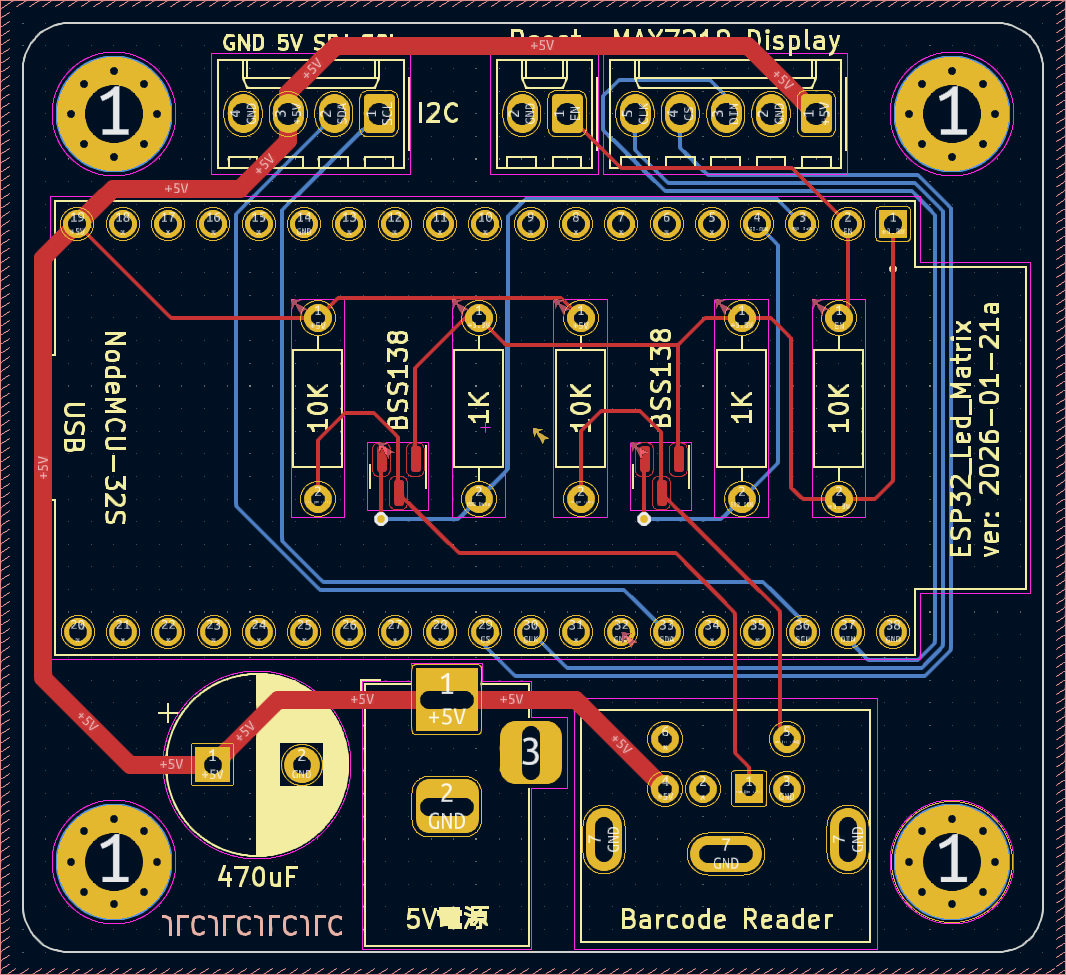
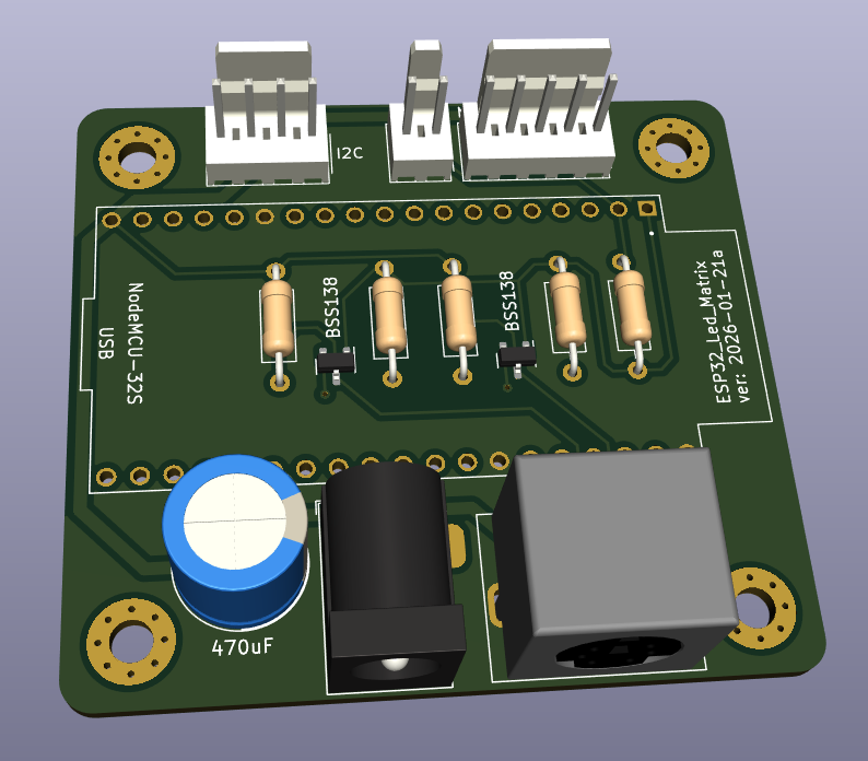
KiCad Esp32 LotNoDisplay is an open-source printed circuit board by Chihhao, from the Chihhao/ESP32-MAX7219-LED-Matrix-Display repository on GitHub. It is a 2-layer board of 57.2 × 52.1 mm with 18 parts on 40 nets, routed with 121 tracks and 2 vias.
It is built around the NODEMCU-32SLUA and BSS138. Its parts include 5 resistors, 5 connectors, 2 transistors, 1 capacitor and 1 IC. It belongs with the radio and wireless boards and the ESP32 and ESP8266 boards of this library.
這是一個基於 ESP32 的 LED 點矩陣顯示專案,整合了 WiFi 網頁設定、RTC 時間顯示、以及條碼掃描器輸入功能,適合用於創客空間或資訊看板。
本專案提供兩種顯示規格的程式碼:
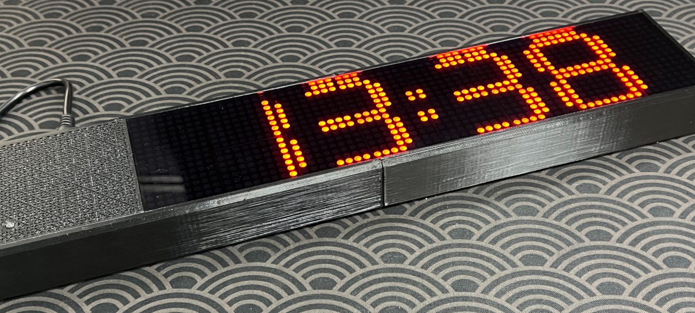
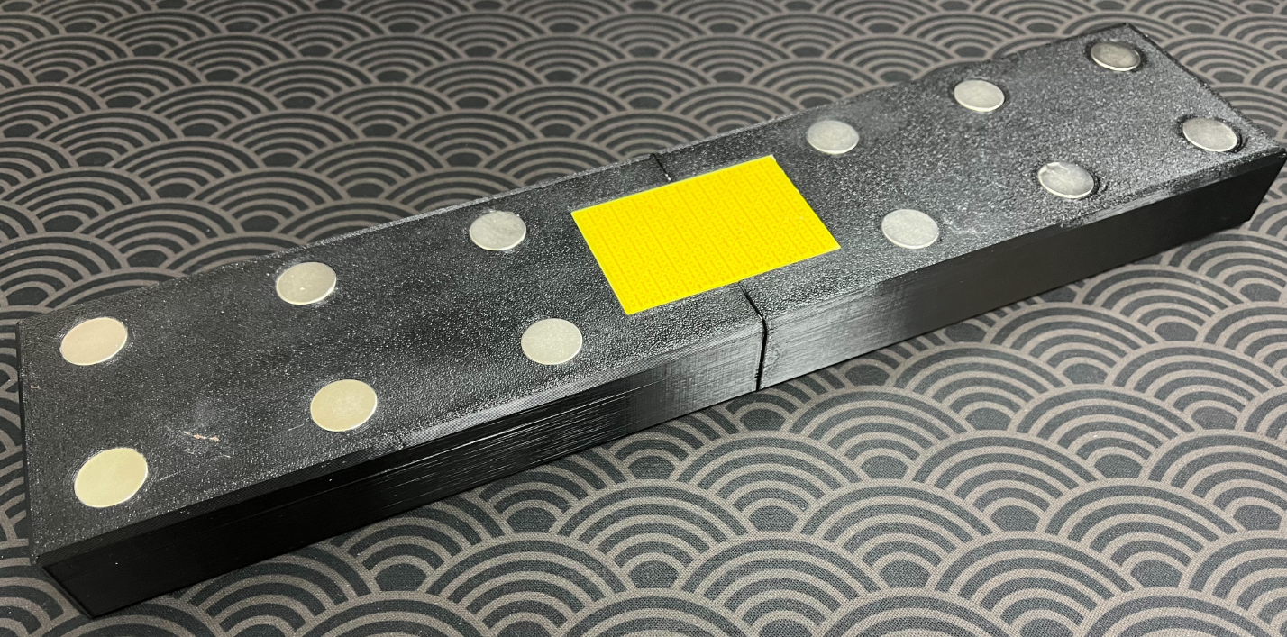
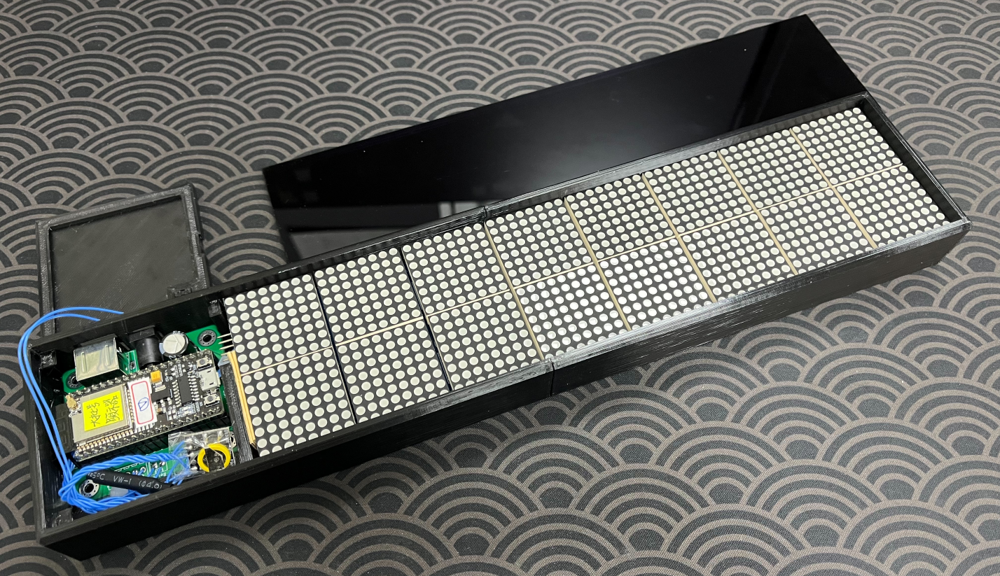
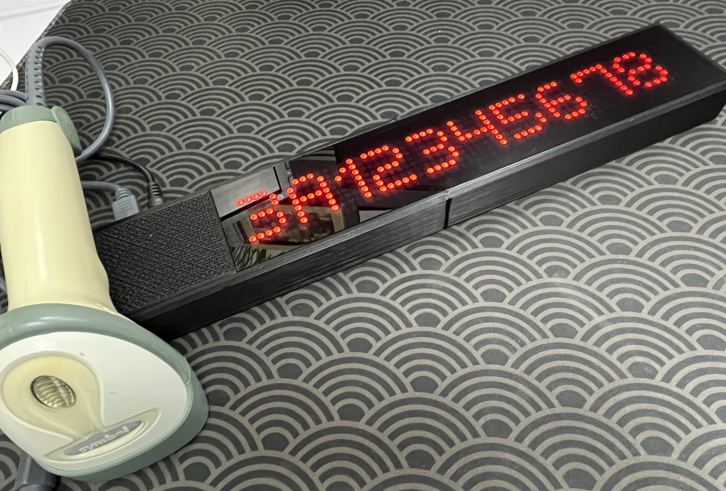
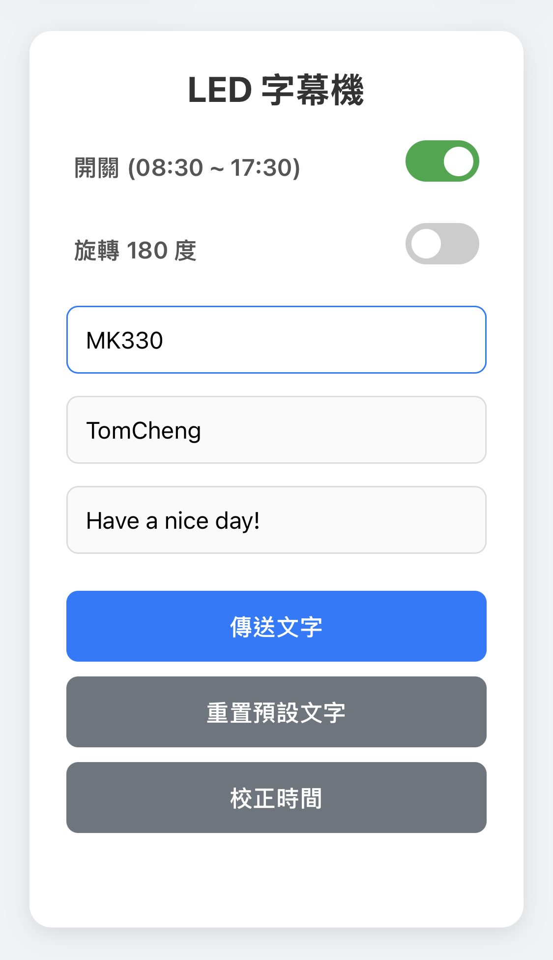
esp32_MAX7219_64x16/esp32_MAX7219_64x8/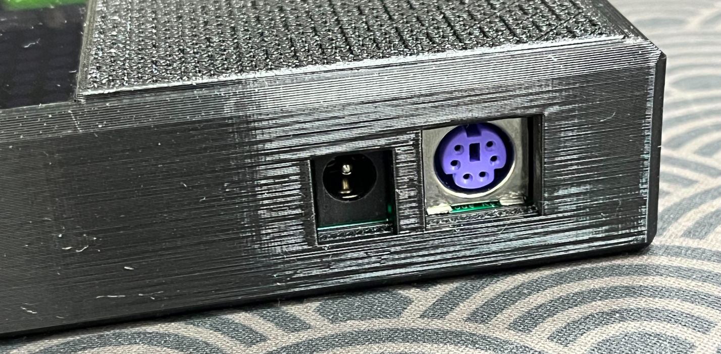
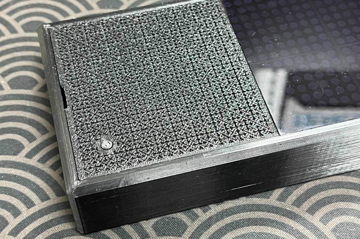
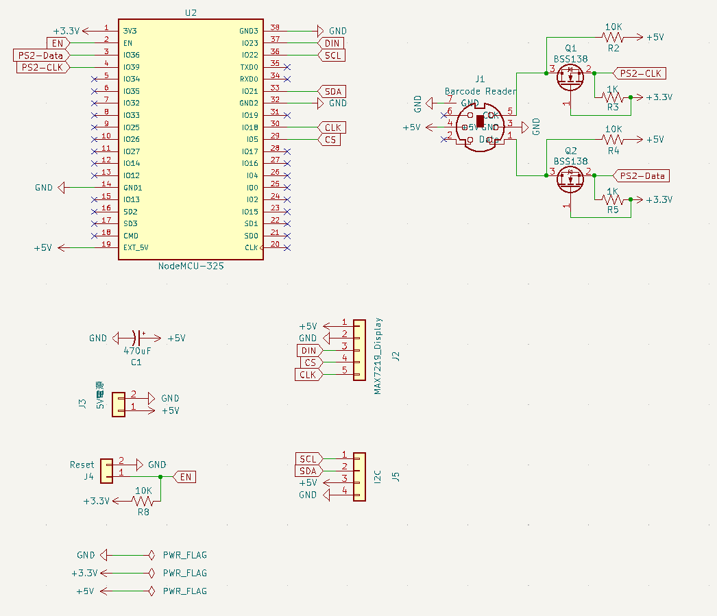
| 模組 | 接腳名稱 | ESP32 GPIO | 備註 |
|---|---|---|---|
| MAX7219 | CLK | 18 | SPI Clock |
| DATA (DIN) | 23 | SPI MOSI | |
| CS | 5 | Chip Select | |
| PS2 Scanner | Data | 36 | Input Only |
| Clock | 39 | Input Only | |
| DS3231 | SDA | 21 | I2C SDA (Default) |
| SCL | 22 | I2C SCL (Default) |
請在 Arduino IDE 中安裝以下函式庫:
註:版本號為開發時使用的版本,建議使用最新版,若有問題可嘗試回退。
MD_Parola by MajicDesigns (v3.7.3)MD_MAX72xx by MajicDesigns (v3.5.1)Bonezegei_DS3231 (v1.0.2)PS2Keyboard (v2.4)Time (TimeLib) (v1.6.1)如果您在編譯過程中遇到錯誤,請參考以下修正方式:
錯誤:narrowing conversion of '49828' from 'int' to 'uint8_t'
PS2Keyboard 程式庫 (v2.4) 原始碼包含特殊符號 '¤',在新版編譯器中會被視為多位元組整數而報錯。PS2Keyboard.cpp (通常位於 Documents/Arduino/libraries/PS2Keyboard/PS2Keyboard.cpp)。
0 /*CapsLock*/, 0 /*Rshift*/, PS2_ENTER /*Enter*/, '¤', 0, '#', 0, 0,'¤' 替換為 0xA4:0 /*CapsLock*/, 0 /*Rshift*/, PS2_ENTER /*Enter*/, 0xA4, 0, '#', 0, 0,錯誤:'class PS2Keyboard' has no member named 'clear'
PS2Keyboard v2.4 不包含 clear() 函式。while(keyboard.available()) keyboard.read(); 取代)。若您使用舊版程式碼或自行撰寫,請留意此差異。ESP32_LedDisplay (64x16) 或 LedDisplay_Nory (64x8)ESP32_LedDisplay (64x16) 或 LedDisplay_Nory (64x8)http://192.168.4.1。isWorkTime() 函式調整時段。| Qty | Value | Footprint | References |
|---|---|---|---|
| 4 | MountingHole | MountingHole:MountingHole_3.2mm_M3_Pad_Via | H1, H2, H3, H4 |
| 3 | 10K | Resistor_THT:R_Axial_DIN0207_L6.3mm_D2.5mm_P10.16mm_Horizontal | R2, R4, R8 |
| 2 | 1K | Resistor_THT:R_Axial_DIN0207_L6.3mm_D2.5mm_P10.16mm_Horizontal | R3, R5 |
| 2 | BSS138 | Package_TO_SOT_SMD:SOT-23 | Q1, Q2 |
| 1 | 470uF | Capacitor_THT:CP_Radial_D10.0mm_P5.00mm | C1 |
| 1 | 5V電源 | Connector_BarrelJack:BarrelJack_Horizontal | J3 |
| 1 | Barcode Reader | Library:Connector_Mini-DIN_Female_6Pin_2rows | J1 |
| 1 | I2C | Connector_Molex:Molex_KK-254_AE-6410-04A_1x04_P2.54mm_Vertical | J5 |
| 1 | MAX7219_Display | Connector_Molex:Molex_KK-254_AE-6410-05A_1x05_P2.54mm_Vertical | J2 |
| 1 | NodeMCU-32S | Library:MODULE_ESP32-DEVKITC | U2 |
| 1 | Reset | Connector_Molex:Molex_KK-254_AE-6410-02A_1x02_P2.54mm_Vertical | J4 |
agustin-arg/Posture
Dispositivo electrónico de corrección de postura corporal

unla-investigacion-desarrollo/ecosistema-iot
Antes de desarrollar el sistema final, realizamos una etapa de exploración donde investigamos y experimentamos con las siguientes tecnologías:


bytecod3/lora-life-jacket
Electronic device for life jackets with LORA data transmission

hopkinskong/eie553-iot-hardware
ESP32 IOT Smart Lock Device Hardware Schematic and PCB used in the course "EIE553 Security in Data Communication".

2026MakerClub/PCB
projects with pcb, custom and commonly used schemes, footprints...etc.

ANTzacalie/termo-pro-esp32
Full-featured smart thermostat built on the ESP32 platform.

It measures 57.2 × 52.1 mm and has 2 copper layers, 1.6 mm thick.
18 parts, built around the NODEMCU-32SLUA and BSS138. The full list of its parts is on this page, with links to each part's symbol and footprint where PCBKit's library has them.
From the Chihhao/ESP32-MAX7219-LED-Matrix-Display repository on GitHub, at the commit this page was made from: the board is KiCad/KiCad_Esp32_LotNoDisplay.kicad_pcb and its schematic KiCad/KiCad_Esp32_LotNoDisplay.kicad_sch. PCBKit opens the board in the browser, with nothing to install.
Its repository states no licence, so its author keeps all rights: ask Chihhao before reusing the design.