A Repository for the Quantum Demonstrator Lite, a Plug and play Quantum Algorythm for Students. Integrates into SpinDrops, a software for simmulating up to three Qubits.
QD lite is an open-source printed circuit board by Cheesylorry, from the Cheesylorry/Quantum-Demonstrator-Lite repository on GitHub, published under the GPL-2.0 licence. It is a 2-layer board of 93.1 × 49.5 mm with 41 parts on 62 nets, routed with 755 tracks and 104 vias.
It is built around the TPS561201DDCR, TPS563200DDCR and 08053C104KAT2A, with the MSAST219LB5106KTNA01, RC0805FR-0710KL and CRCW080533K2FKEAC among its other parts. Its parts include 4 resistors, 2 ICs, 2 connectors, 2 inductors and 1 switch. It belongs with the RP2040 boards of this library.
A Plug and play Quantum Algorithm Demonstrator for Students. Integrates into QuBeads, a software for visualising up to three Qubits, with fully customisable Quantum Gates.
Picture of the Setup used at the Max Planck Institute of Quantum Optics
The Quantum Demonstrator Lite can be used to demonstrate algorithms up to three Qubits over seven positions, and these can be viewed in Detail with the QuBeads Software, available at https://spindrops.org/2.5.0-beta1/download.html(We recommend going with the Beta, as it has the updated visualisation)
text
NOTE: The final product is to be used with QuBeads, the successor to SpinDrops. The auto Update is not available in SpinDrops but is on the ToDo for QuBeads.
The Quantum Demontrator Lite utilises 21 RC522 readers to maximise flexibility with the Quantum gates, allowing you to create your own custom gates. These are being controlled by a Raspberry Pi Pico2 Microcontroller, which in turn communicates with the PC over USB.
It was designed to be somewhat affordable to institutions and Schools, with a price around 400€ depending of the suppliers you choose, and the means of assembly.
Getting Started
For anybody wanting to build the Demonstrator, you should have a few prerequisite Tools:
Tool
3D Printer
Ideally one with a Printbed bigger than 300x250, but 250x250 can also accomodate all parts. The ability to Print Mulit Colour is also very Helpful for printing the Gates
Soldering Iron
A fine tipped Soldering Station/Iron is necesary, should you decide to assemble the PCB yourself, Solder flux, tweezers, tin snips and more standard Soldering tools are required
Hex Bits
A standard Metric Set of Hex bits
Note: Should you decide to assemble the PCB yourself, be aware the SMD components are not the easiest to work with. A revamped version is a WIP which will drastically reduce the amount of components needed
Electronics
|Electronics/ contains the PCB Schematic and Board design. The PCB was designed in KiCad.
Parts needed for the PCB can be found via the Schematics, the BOM or here.
Main PCB (Current state)
The current State is functional, but a simpler V2 is being worked on.
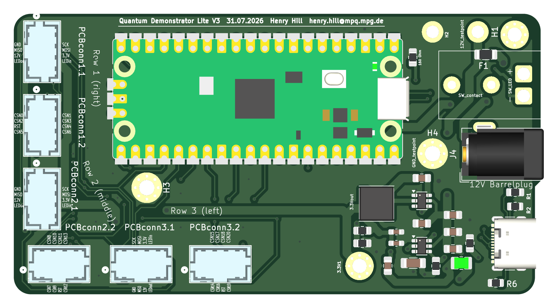
The Main PCB contains the Raspberry Pi Pico and all the power conversion needed to power the NFC readers, the LEDs and the Pi Pico itself.
For a complete PCB assembbly service, you can expect to pay ~85€
Parts 1, 8, 11, 12 and 19 will have to be hand soldered. Numbers 8, 9 and 12 are Normal THT components, 19 has to be wired and then soldered.
The Raspberry Pi Pico2 has an Unusual way of soldering it to the PCB, due to the assumption one doesn't have a hotplate available.
Top Side
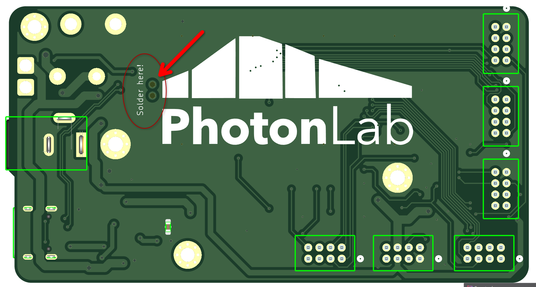
Bottom Side
Marked by the red Arrow are two through Holes, these must be kept unfilled, double check this when ordering the PCB
First solder down two of the SMD Pads of the Pi Pico, then turn the board around and fill the Marked through holes with solder, make sure to keep it warm for a bit, and probe the PCB for connection between the USB and the data pins on the Pi Pico.
Connecting PCBs
The Quantum Demonstrator uses three almost identical PCBs to connect the individual NFC Readers to the Main PCB. These Connecting PCBs also mount the LEDs for the illumination. While all of the Connecting PCBs are the same, the Placement of the connectors is different for one of the three boards.
These connectors are labeled with A.1, A.2 and B.1, B.2. This is neccessary due to cabeling and space saving.
Two Boards must be configured with the A.1 and A.2 ports soldered and one Board with the B.1 and B.2 ports
Important Note for the NFC readers: These must be the JoyIT readers, as the pinout is not compatible between different vendors. The ones we specify have to have straight Through hole connectors, you can desolder the included conneectors or order via JoyIT directly and ask to have these connectors omitted, such that you can solder your own.
BOM of Assembly 1, List of Parts to 3D print marked in Red (🔴)
Todo: Link Parts in here to parts in Project
On the Prusa XL this would need 4-5 Printbeds
Assembly of the Case
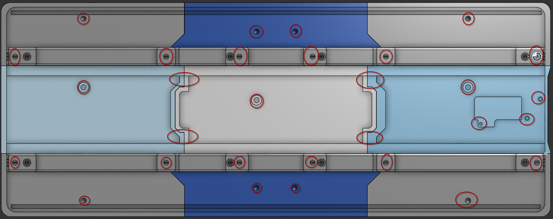
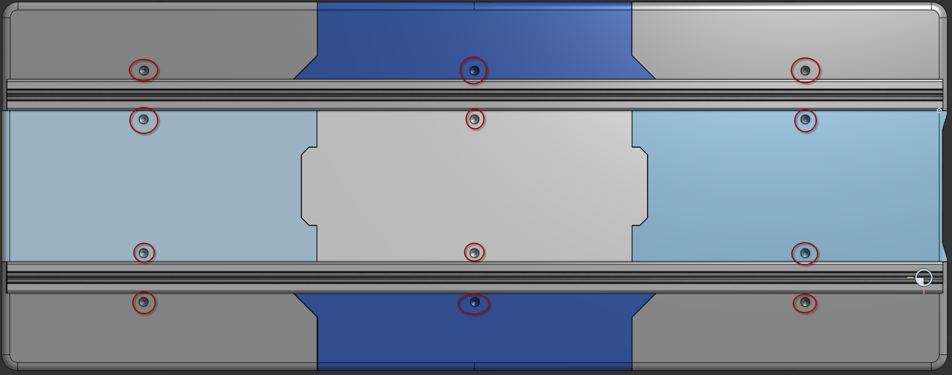
Heatset Inserts
In preperation for assembly, insert the threaded Heatset Inserts into the pre made holes.
For this set your soldering iron to aroun 250°C and slowly but firmly melt and press the insert into the hole. Try to keep it as level as possible to the Surface. The Following pcitures show where to position the Inserts.
Top Side
Bottom Side
Connection to the Aluminium Extrusion
There are multiple screwholes from the outside accessing the Aluminium extrusion. Insert the Matching screw, at a T-Nut onto it, and slide it onto the Aluminium Extrusion.
Start with the Shoulder Sections, then do the middle section, then the Feet to tie it all to gether. Only put the lid on right at the end.
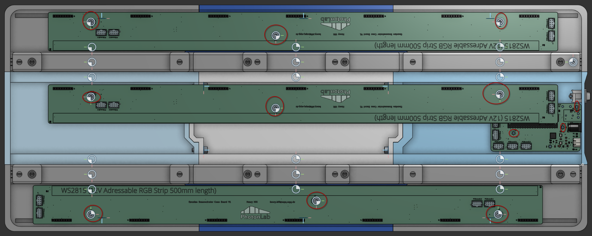
Mounting of PCBs
The Connection PCBs are screwed down with three M4 Screws, while the Main PCB is screwed down with three M2 screws.
Installing LEDs
Glue the LED strip down on the marked region. Make sure the Pinout is correct, adn solder it to the given Pads.
To aid in diffusion a Thin plastic sheet is glued to the back of the Lid pieced to coder the Lighting slits (A piece of paper also works).
Software
The Quantum Demonstrator requires some Embedded and some PC side software.
Prerequisites
Software
PlatformIO
A means to flash the C++ onto the RaspberryPi Pico via USB e.g. PlatformIO in VSCodium
Python 3.14
or newer. Needed for the PC Side software
Tkinter 3.14
or newer. Needed for the GUI on the PC side
Embedded Software
Flash the C++ Program main.cpp onto the Raspberry Pi Pico 2 via USB.
Download the desired Gates from /CAD files/Quantum Gates/ and 3D print them. Then glue An NFC Tag into each Indent (on single Qubit gates only one, on Mulit Qubit gates two or even three)
Using the Quantum Demonstrator (Work in Progress)
Connect the Demonstrator to 12V power and USB, and Turn it on
Start python main.py and select the USB device in the dropdown Menu, and check if you can see Gates appear when you place them on the readers.
"The Autowrite Json" automatically writes the JSON ever time an update is registered. This means you can continously import these files into spindrops.The directroy it deposits the files in can be chosen on launch.
Now Start spindrops and import the newly generated QD_output.json File.
Congratulations! You now have a functioning Quantum Demonstrator.
Enrolling New Gates into the Database (Heavy Work in Progress)
Run
python enroll.py --port /dev/ttyACM0
and then follow the instructions. The Names are only Important if you want to designate your own gates via the spin drops Syntax.
Real World Gate
Database Shortname to use
Hadamard
H
Not
X
Phase
Phase([deg])
Known Issues / ToDo
When enrolling gates the UUID gets entered incorrectly. Fix: Use multiple reads and verify against each other - Temporary fix, reenroll the gate.
ToDo
Add GUI to the enroll process
Fix framing issues in gui.py
Package as Binary
Proper spindrops integration -> WIP
Revamped PCB (HEAVY WIP)
to lower the costs of single piece production move from custom designed Voltage conversion to premade TRACOS.
Staged Design 12V -> 5V -> 3.3? vs Drirect Design 12V -> 5V and 12V -> 3.3V
A Repository for the Quantum Demonstrator Lite, a Plug and play Quantum Algorythm for Students. Integrates into SpinDrops, a software for simmulating up to three Qubits.
Firmware for Fail-secure door controller of access control room. Activate when power outage is occured.
82 parts
Questions
How big is the QD lite PCB?
It measures 93.1 × 49.5 mm and has 2 copper layers, 1.6 mm thick.
What parts does the QD lite use?
41 parts, built around the TPS561201DDCR, TPS563200DDCR, 08053C104KAT2A and MSAST219LB5106KTNA01. The full list of its parts is on this page, with links to each part's symbol and footprint where PCBKit's library has them.
Where can I download the QD lite KiCad files?
From the Cheesylorry/Quantum-Demonstrator-Lite repository on GitHub, at the commit this page was made from: the board is Electronics/Main_PCB/QD-lite.kicad_pcb and its schematic Electronics/Connection_PCB/Conn_PCB.kicad_sch. PCBKit opens the board in the browser, with nothing to install.
Can I use the QD lite design in my own project?
Its repository publishes it under the GPL-2.0 licence: you may reuse it on that licence's terms (keep the author's notice, and for a copyleft licence share your changes alike).


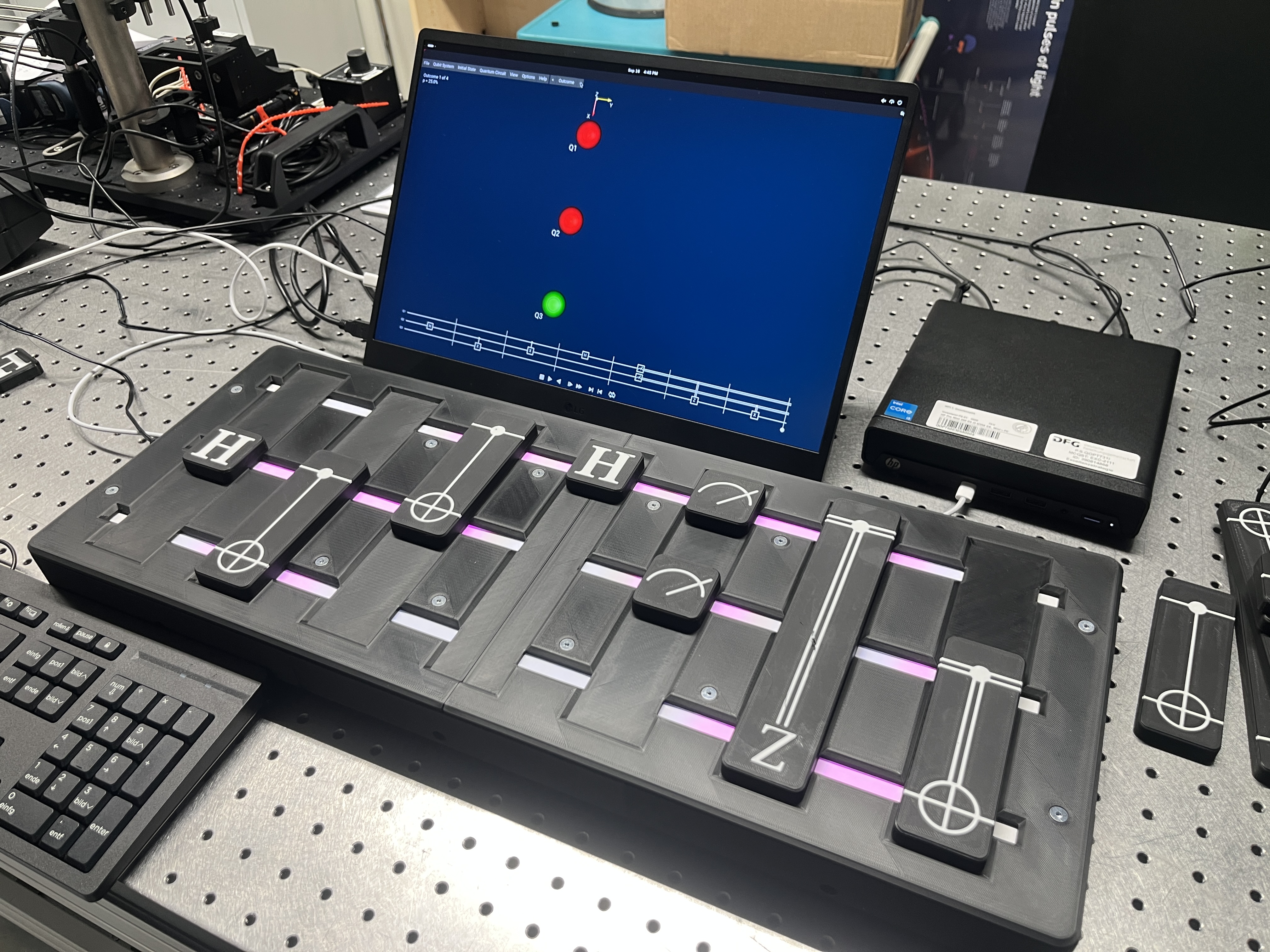 Picture of the Setup used at the Max Planck Institute of Quantum Optics

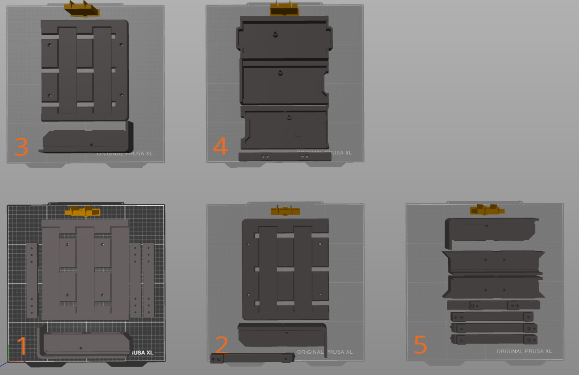 On the Prusa XL this would need 4-5 Printbeds
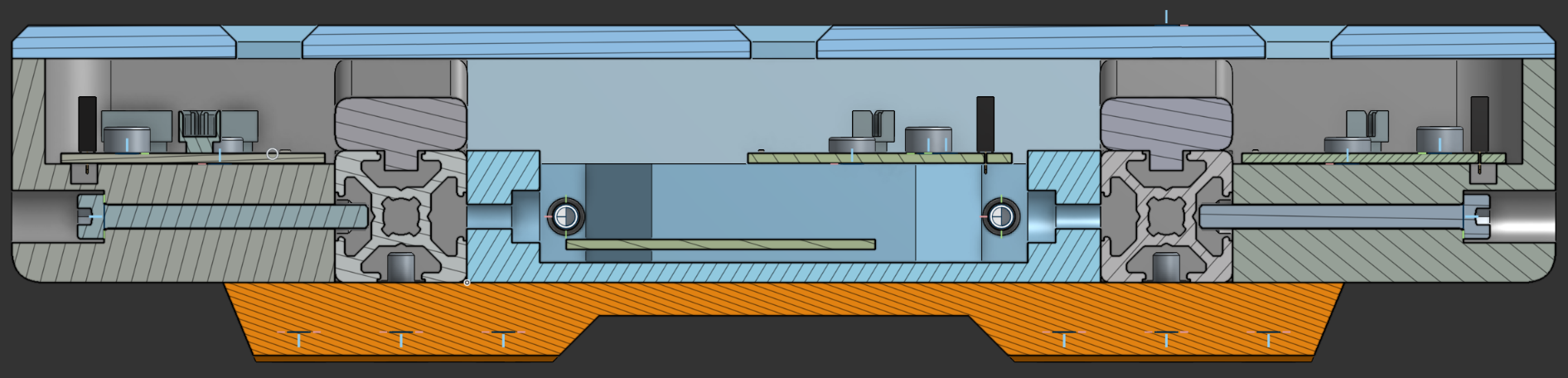 There are multiple screwholes from the outside accessing the Aluminium extrusion. Insert the Matching screw, at a T-Nut onto it, and slide it onto the Aluminium Extrusion.
Start with the Shoulder Sections, then do the middle section, then the Feet to tie it all to gether. Only put the lid on right at the end.
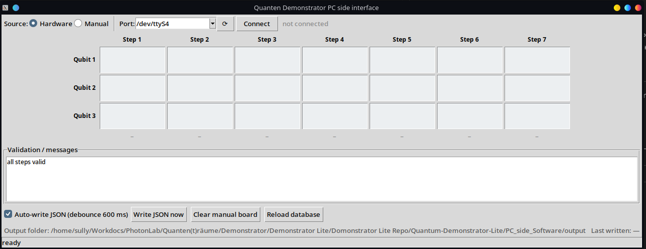 "The Autowrite Json" automatically writes the JSON ever time an update is registered. This means you can continously import these files into spindrops.The directroy it deposits the files in can be chosen on launch.
Now Start spindrops and import the newly generated QD_output.json File.
Congratulations! You now have a functioning Quantum Demonstrator.


