


2 layers48.1 × 120.3 mm
Open rad detector
CarlosGS/Open-Radiation-Detector
Portable radiation detector based on an ionization chamber
23 parts65

 CarlosGS/Open-Radiation-Detector65
Portable radiation detector based on an ionization chamber
Open rad detector is an open-source printed circuit board by CarlosGS, from the CarlosGS/Open-Radiation-Detector repository on GitHub. It is a 2-layer board of 48.1 × 120.3 mm with 34 parts on 25 nets, routed with 259 tracks and 29 vias.
It is built around the LM3914V and FMMT734. Its parts include 10 diodes, 6 resistors, 5 capacitors, 3 ICs and 3 connectors.

Portable radiation detector based on a ionization chamber.
The KiCad PCB sources and BOM can be found in the repository's subfolders.
Check out https://hackaday.io/project/27508-open-radiation-detector for more information.
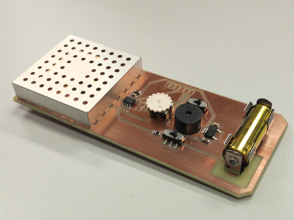
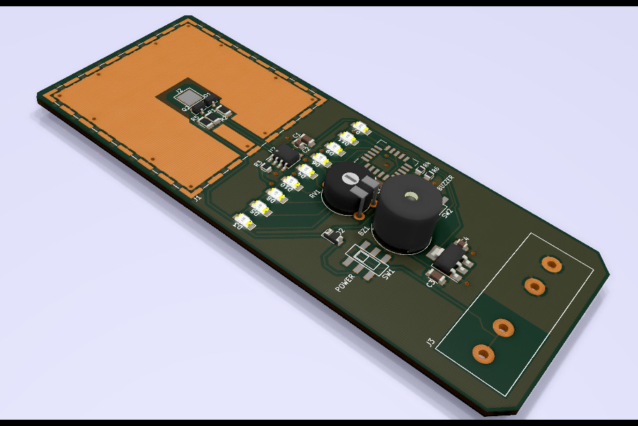
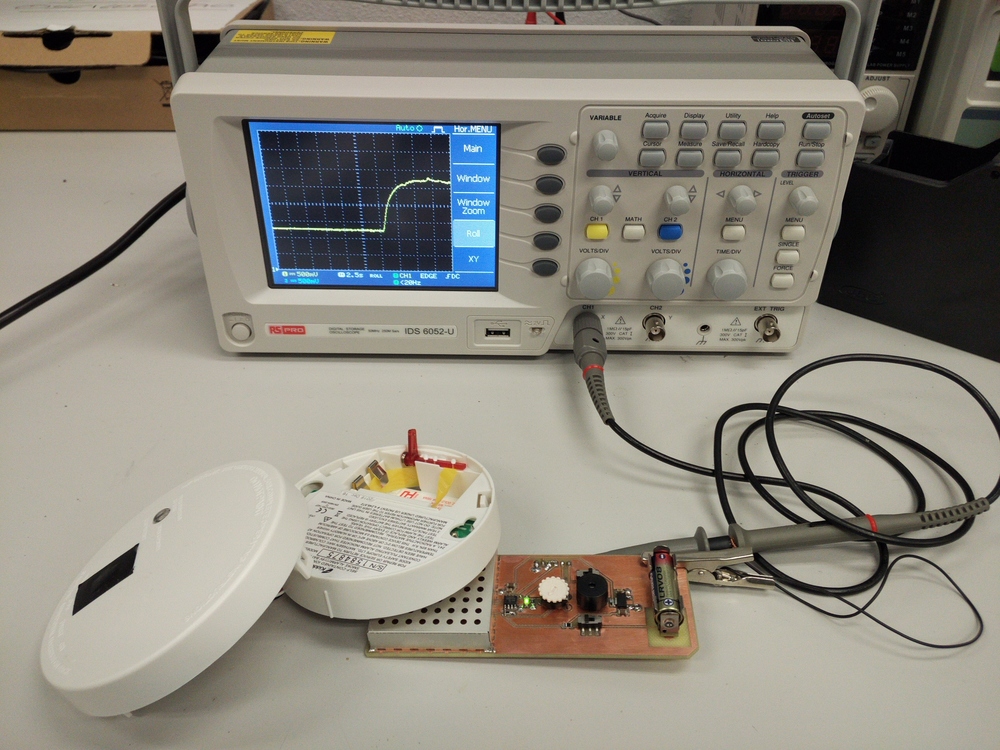
October 2017: Designed, build and document a prototype to participate in the Hackaday Prize.
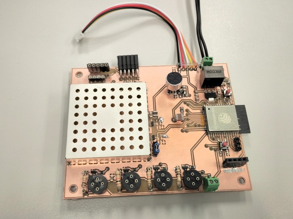
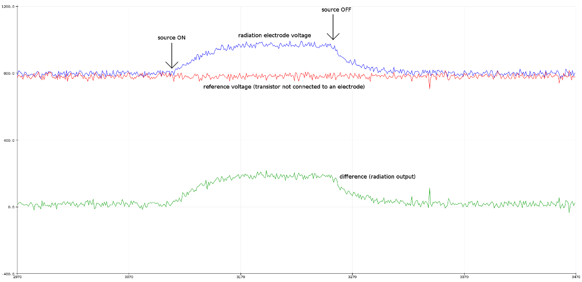
5/May/2017: The radiation sensor concept has been incorporated into a connected sensor board. It looks like the effect of nearby electrostatic fields still affects the voltage output, regardless of the back plane being connected to either guard voltage or ground (maybe this is due to the large size of the electrode?). The board uses the PNP configuration polarized with 10 MOhm 1% and an op-amp driver (LM2904DR) to minimize the effect of ADC current consumption. It includes a duplicate circuit unconnected from the electrode, to be used as a compensation for temperature effects.
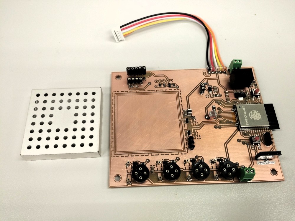
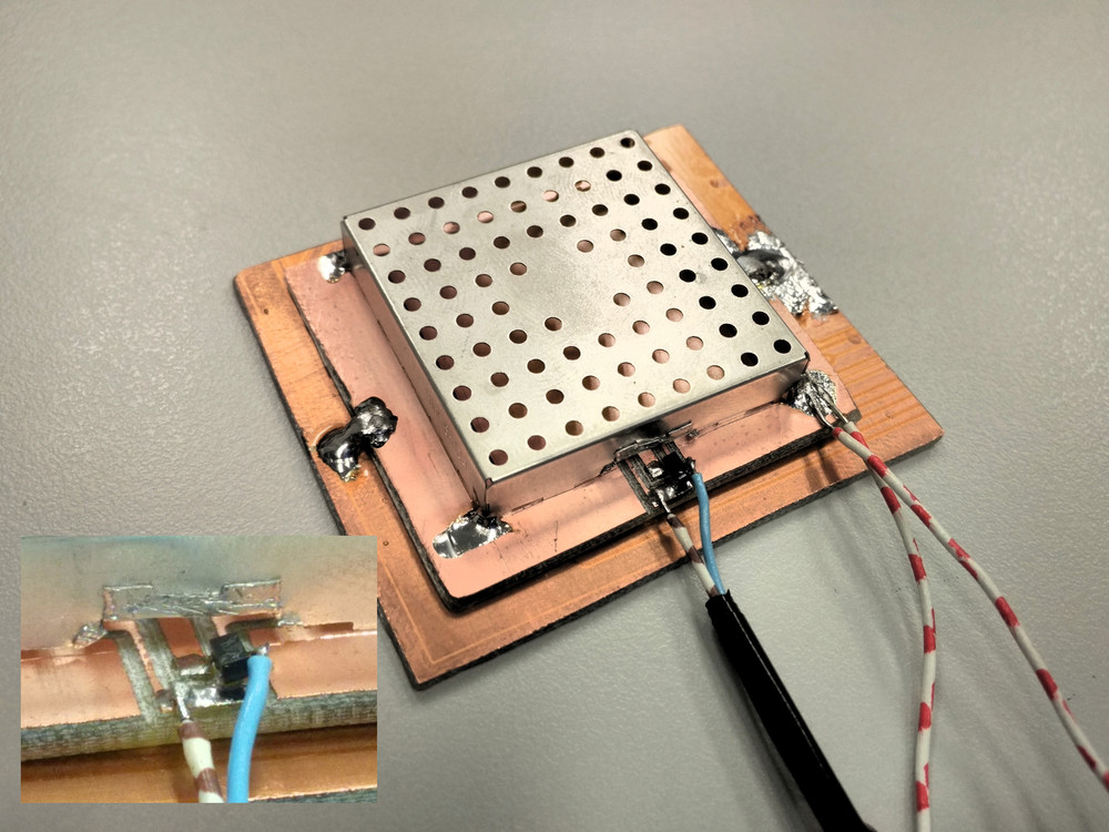
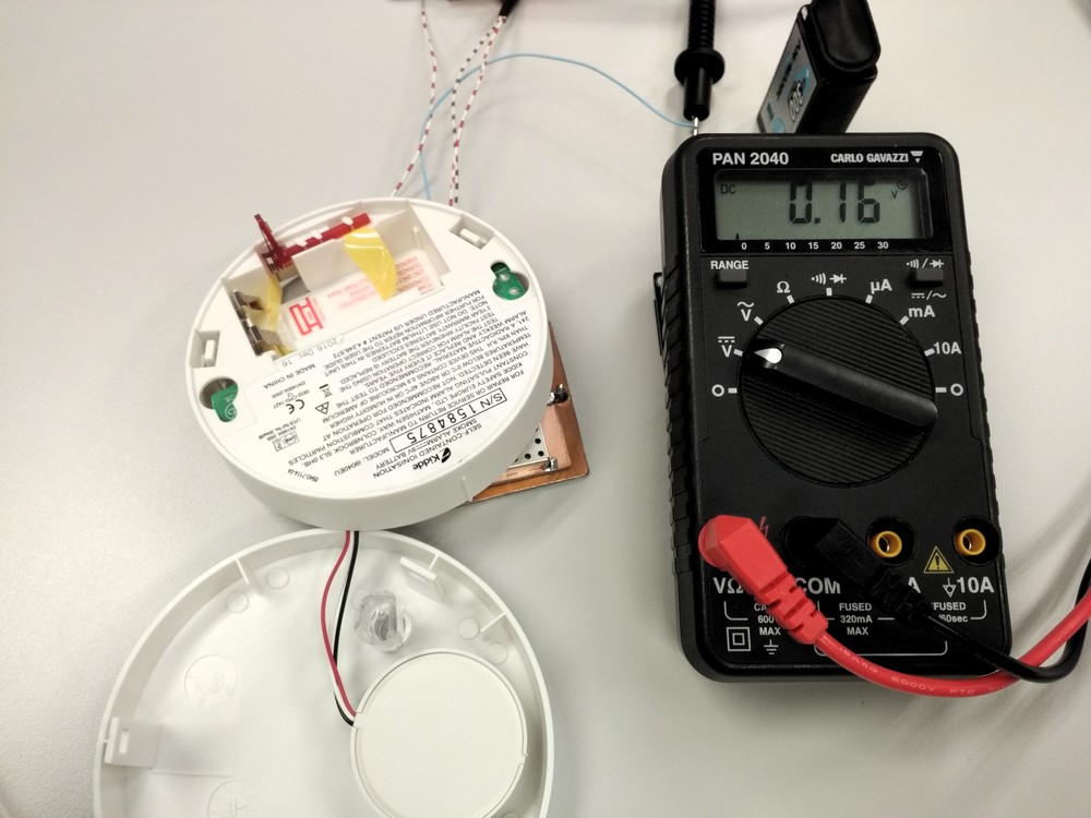
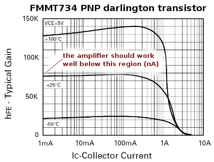
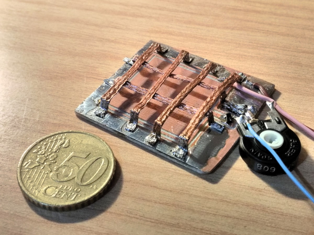
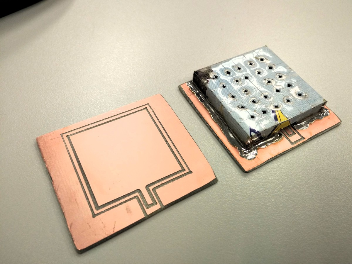
On a second thought, the "finger electrodes" may not be a good idea. Since there is a large contact area between each finger, there surely is a lot of leakage current that will mask-out any ion-induced current (one of the biggest concerns explained by Charles Wenzel's ion chamber website)
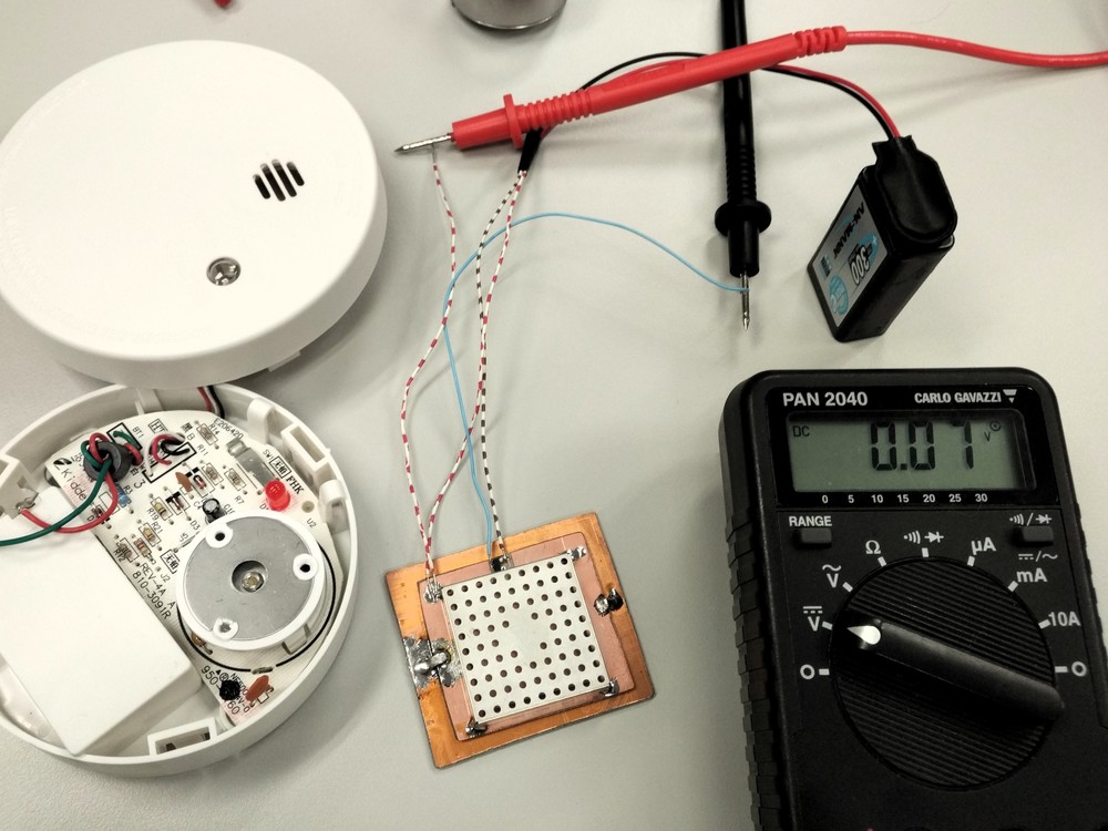
19/Jan/2017 Finally got a .9uCi AM241 source to test, it will be the benchmark for the detector. Unfortunately, the first attempts with the amplifier circuit yield very noisy measurements, that mainly depend on wind and humidity. Surprisingly (to me), it is also very dependent on static electricity. I've also tested again the spark particle detector, but there seems to be absolutely no relation between the sparks and the proximity of the radiation source. Maybe the finger electrodes are too "pointy" because of the manufacture method (milling)? pic1 pic2
Week of 9/Jan/2017: Simulation of circuit amplifiers "click type", "LED scale type"
Self-ask the question: How to make a simple low-cost radiation detector? Begin to learn about ionization chambers thanks to Charles Wenzel's website.
Week of 1/Jan/2017: First learn of spark particle detectors. Design, build and test a PCB electrode (but without any radiation source to be tested). video
This work is licensed under a Creative Commons Attribution 4.0 International License. https://creativecommons.org/licenses/by/4.0/
Garcia-Saura, C. (2017). Open Radiation Detector. GitHub. https://doi.org/10.5281/ZENODO.10446305
Latex / Bibtex citation:
@misc{garciasaura2017rad,
  author = {Garcia-Saura, Carlos},
  title = {Open Radiation Detector},
  publisher = {GitHub},
  year = {2017},
  doi = {10.5281/ZENODO.10446305},
  url = {https://doi.org/10.5281/ZENODO.10446305}
}| Qty | Value | Footprint | References |
|---|---|---|---|
| 9 | LED | LEDs:LED_1206 | D3, D4, D5, D6, D7, D8, D9, D10, D11 |
| 3 | 10u | Capacitors_SMD:C_1206 | C1, C3, C5 |
| 2 | 100n | Capacitors_SMD:C_0805 | C2, C4 |
| 2 | 10M | Resistors_SMD:R_1206 | R1, R2 |
| 2 | FMMT734 | TO_SOT_Packages_SMD:SOT-23 | Q1, Q2 |
| 1 | 33u | Inductors_NEOSID:Neosid_Inductor_SM-NE29_SMD1008 | L1 |
| 1 | BUZZER | SW_JS202011SCQN:SW_JS202011SCQN | SW2 |
| 1 | Batt | A23_battery:A23_battery | J3 |
| 1 | Buzzer | Buzzers_Beepers:MagneticBuzzer_ProSignal_ABI-010-RC | BZ1 |
| 1 | D | Diodes_SMD:D_1206 | D2 |
| 1 | Electrode | SMD_Packages:1Pin | J2 |
| 1 | LD1117S50TR_SOT223 | TO_SOT_Packages_SMD:SOT-223-3_TabPin2 | U1 |
| 1 | LM3914V | Housings_LCC:PLCC-20 | IC1 |
| 1 | LMR1 | Resistors_SMD:R_0805 | R4 |
| 1 | LMR2 | Resistors_SMD:R_0805 | R6 |
| 1 | MCP6N11 | Housings_SOIC:SOIC-8_3.9x4.9mm_Pitch1.27mm | U2 |
| 1 | Outer_Shield | Shielding_Cabinets:Laird_Technologies_BMI-S-107_44.37x44.37mm | J1 |
| 1 | POWER | SW_JS202011SCQN:SW_JS202011SCQN | SW1 |
| 1 | R_F | Potentiometers:Potentiometer_Trimmer_Piher_PT-10v10_Horizontal_Px10.0mm_Py5.0mm | RV1 |
| 1 | R_G | Resistors_SMD:R_0805 | R3 |
| 1 | Rtune | Resistors_SMD:R_1206 | R5 |
CarlosGS/Open-Radiation-Detector
Portable radiation detector based on an ionization chamber


mjmorano/Precision-Current-Source
Once it's uploaded connect the Arduino pins to the 6 pin header on the current source as follows:

jerry20091103/Teensy_Grovebox
A portable synth and music multi-tool made with Teensy 4.1

DenKen-NITNC/EleMagHarmony
Band Instrument (Part) : - Stepping Motor (Melody) - Solenoid (Guitar) - Floppy Disc Drive (Base) - Relay (Drum)

kbroomm/Single-Cell-Li-ion-Charger
KiCad PCB design for a single-cell lithium-ion battery charger, with a 5V USB-C input and 10-LED charge level indicator.


FrameworkComputer/ExpansionCards
Reference designs and documentation to create Expansion Cards for the Framework Laptop
It measures 48.1 × 120.3 mm and has 2 copper layers, 1.6 mm thick.
34 parts, built around the LM3914V and FMMT734. The full list of its parts is on this page, with links to each part's symbol and footprint where PCBKit's library has them.
From the CarlosGS/Open-Radiation-Detector repository on GitHub, at the commit this page was made from: the board is Detector_PCB_1.0/open_rad_detector.kicad_pcb. PCBKit opens the board in the browser, with nothing to install.
Its repository states no licence, so its author keeps all rights: ask CarlosGS before reusing the design.