2 layers100 × 100 mm
Alarm btn
Carabouille/Alarm_Clock_dawn_simulator
A description of my Alarm clock with dawn simulator for the Fallout event organised By Hackclub
55 parts

 Carabouille/Alarm_Clock_dawn_simulator
A description of my Alarm clock with dawn simulator for the Fallout event organised By Hackclub
Alarm clock is an open-source printed circuit board by Carabouille, from the Carabouille/Alarm_Clock_dawn_simulator repository on GitHub. It is a 2-layer board of 100 × 80 mm with 75 parts on 81 nets, routed with 694 tracks and 213 vias.
It is built around the ESP32-S3-WROOM-1-N8, MT3608 and VEML7700-TT, with the AMS1117-3.3, DW01A and FS8205A among its other parts. Its parts include 20 resistors, 18 capacitors, 10 connectors, 9 ICs and 9 diodes. It belongs with the lEDs and displays boards and the ESP32 boards of this library.


Hello, I'm Carabouille, a French guy who loves tech and hardware, and this is my GitHub to present you my project for Fallout! I'm gonna present you my alarm clock with dawn simulator feature!
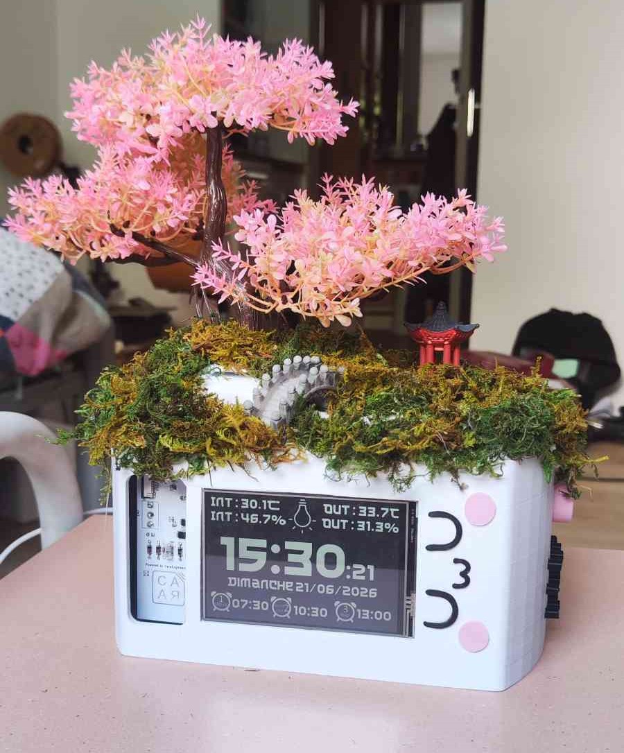
AND see just how beautiful it is !!! Yeah I know I did a great job you can tell me ^^
And to see how it works in details you can watch the video that I did on my alarm clock : (CLICK ON MY AWESOME FACE !)

I often have trouble waking up with my phone alarm. I often feel that I'm tired even though I slept a lot. And this is for a very simple reason: our brain is not a machine, he can't wake up so fast. He works on cycles. And our phone alarm gets him off very fast during this cycle. A better way to wake up more naturally is with the solar light (but the night I close the rolling shutter for the cold). So a solution to this issue is to use an alarm clocker with a dawn simulator feature to increase the brightness of the room over time to wake up your brain gently, but problem : Tis type of alarm clocks is really expensive (over 100 euros), so I told myself that it is the perfect occasion to create my own ALARM CLOCKS WITH A DAWN SIMULATOR!!! And I'm gonna add a lot of features like:
I really can't wait to build my project, develop my skills and learn so much! I'm gonna give the best version of myself to be proud of my alarm clocks and I also hope that I will have the chance to go to Shenzen to meet other hardware fans! Kind regards, your French friend, Florian "Carabouille" CHARLES :))
The better way to describe my project is with a poster who talks about it! I'm not a good designer, but I think that I made a good poster
ET VOILA :
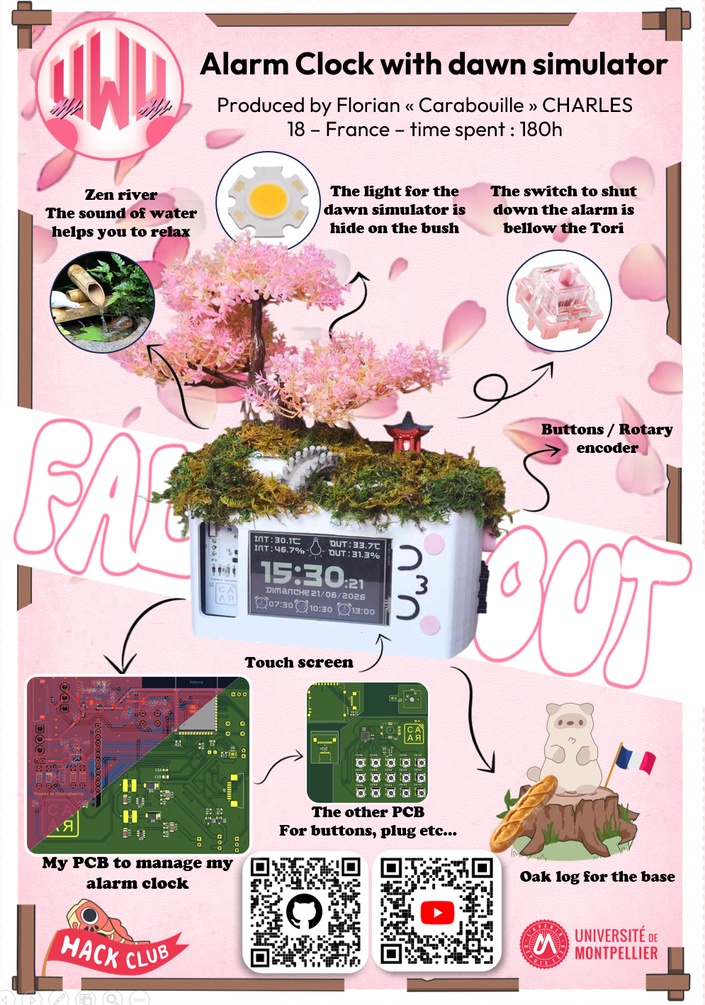
The design idea is pretty simple: the alarm clock in the center and some arrows to explain the different parts of the project I explain here 7 features:
My favourite color is the pink (hard to guess ^^) I really love the cherry flower in the background that reminds me of the cherry tree on the top of the alarm. The UwU logo is everywhere cause with my friends it's a private joke since a few years. I love the way that the "Fallout" goes behind the box.
Is not perfect of course but for my light skills in design I think it's really nice, I'm proud of it !
One of the main parts of my project is the CAD! For this I used the software Solidworks ( a French soft! COCORICO!) I'm in a toxic relationship with Solidworks, sometimes I love it, sometimes I hate it... This software is not easy to use but after some crashes and bugs I finally made a CAD which I'm proud of
So for my project I had to work within certain constraints
And with all that, I need to find a good idea for design
My first idea was a shape like the giant telescope, like we can see in the American desert. But I have never obtained a result that I like
So I completely changed my idea to have a Zen garden on the top of my alarm clock With a tree, plants, and a river!
It looks like this :
<img src=Pictures/box.png width="400"/>
yes that is not the same as on the zine page, Solidworks is not really good at rendering
But all the parts are here and I even find it cool! I really love that the PCB is not hidden by all the cases, it's cool to see it
On this picture we can see : the screen, the PCB, the UwU logo, the oak log and the buttons on the side
If we move to the top we can see the Zen garden
<img src=Pictures/top_box.png width="400"/>
We can see :
The servo motor is here to hide the light during the day with moss on it. And when is it the time to turn the light on the servo motor move the piece of plastic with moss on it that hides the light to let the light illuminate the room. So the light system is invisible during the day!
The servo motor is not hidden by the case cause the moss will recover it.
And on the switch I'll put a little Japanese temple like we can see on the poster.
Let's make the walls transparent to see what is inside the box!
<img src=Pictures/top_box2.png width="400"/>
<img src=Pictures/back_box.png width="400"/>
Yes, there are a lot of things inside it!
We can see well in the first picture the servo motor as we saw earlier And the light with the heat sink, which is carried by a support with screws to the box The heat sink is necessary here cause the light needs to be at least a 8W to diffuse a minimum of the light to wake you. But the light is also powered on 24V and if you do the calcul
P = U * I
I = P / U
I = 8 / 24 = 0,33 A
It's a lot for a little LED COB ! It can heat up to more than 100 degrees. With the heat sink, everything will be ok!
If we watch the second picture we can see the other components
Like the speaker, even if the light is supposed to wake you. If you sleep very deeply, good music is necessary to wake up! We can see on the left the PCB buttons for all the buttons and the knob. Is linked with the main PCB with a FPC cable.
The huge tank in the middle is for the water of the river. The pump is also inside. The holes are for the pipes.
We can see the USB C port in the bottom right also linked with the main PCB with a FPC cable.
On the right we have the PCB for the SD card. And below it we have our battery. The battery is just in case that there is a power cut at home, the battery will supply the system until the return of power !
And that's already a lot for a CAD, but I'm really proud of me! I can't wait to print it!
OK so now it's the moment to talk about my PCB! And it's a huge part of my project! It's only my second PCB so it's not perfect, the first was the macropad.
<img src=Pictures/pcb_elec_1.png width="1000"/>
This is only the main PCB, and I'm going to describe all the different parts I'm not gonna describe how I chose the components because it's not really important, but for each component I had to follow the datasheet.
So we can see at the top left the port J1 that brings the power supply from the USB C port on an other PCB. The power is sent to the first components the MCP73871. This component charge at the same time the battery in 4,2V and supplies the system with the 5V
But 5V is too high for an ESP32, so we need to decrease it to 3,3V with the AMS1117-3.3.
For this project I used an ESP32-S3-WROOM-1 that is very powerful and the WiFi connection will help me to search for the local weather.
For the speaker, we need to use an audio amplifier. I chose to use the MAX98357A, which is very famous for this type of project
I used a DW01A and a FS8205A, this duo of components is for the battery. To avoid overload, deep discharge, and protection from the short circuit.
For the LED and the fan of the heat sink I need 24V and 12V. So I used a 2 MT3608 to increase the voltage.
To control the led I'll use 2 channels of PWM to manage the warm and cold colors of the led. To do this I'm gonna use a 2 transistors A03400A.
I also use a VEML770 a light sensor to manage the luminosity of the screen.
We also have a lot of connectors for the :
You can see two footprint for a switch (SW3 & SW4), if you wish to switch off the main power supply or just the battery power supply (!YOU NEED TO PLACE IT ! else the circuit is open)
And after having done the wiring diagram, it's time to root all the components between them!
This is my final solution:
<img src=Pictures/pcb_pcb_1.png width="1000"/>
<img src=Pictures/pcb_pcb_2.png width="500"/> <img src=Pictures/pcb_pcb_3.png width="500"/>
We can see here all the components which I mentioned earlier I root on 2 faces so it's not too difficult to do it. The main difficulty is to match the footprint with the real component.
And that's all for the main PCB. It's already a lot!
Let's talk about the second PCB, The Buttons PCB!!
This PCB is simpler than the previous one, it is just a little repetitive with all the buttons We can see here the wiring diagram!
<img src=Pictures/pcb_elec_2.png width="1000"/>
You can see here 4 different PCBs separated by the blue lines. The larger is the PCB with all the buttons and the polar. Also, I used a MCP23017 to increase the number of pins GPIO of the ESP32 ( I used a lot of buttons ^^) I'll go into detail in the firmware part. You can see a capacitor in parallel for each button. It's anti-bounce material. It's very important for a professional project! I added on this PCB an AHT 20, it's a temperature and humidity sensor.
The little PCB in the middle is for the switch on the top of the box.
The PCB on the bottom is the micro SD port card PCB
and the last is the PCB for the USB C
And after this it's rooting time !
<img src=Pictures/pcb_pcb_4.png width="1000"/>
<img src=Pictures/pcb_pcb_5.png width="500"/>
<img src=Pictures/pcb_pcb_6.png width="500"/>
That wasn't possible with the dimensions I needed to avoid the waste of some part of the PCB, like you can see the part not used. I'm gonna cut the different PCB myself with a dremel.
The Firmware is a big part of my project! (I said it for each part ;-;) To code I used the software Visual Studio Code and the extension Plateformio The code is pretty simple for the moment. I only initialize all the components. I'm gonna add all the interesting features when I could have the card in my hands. For the moment, given that I only initialize the components, all my code parts are just from the example code that I found online and from old code that I made.
In the code I initialize :
There are still a lot of things to add. I will add this later (with components in front of me) cause it is code more complicated, and it's useless to code this without debugging in live (I guess)
The things that I need to add:
Now it's the time to do the BOM and order all our components!
I mainly used this site :
I split the BOM into different parts.
The first part is the components that I'm going to order on LCSC (Overall, these are the CMD components)
| Components LCSC : | name | value | Quantity | LCSC code / link | price (€) | |
|---|---|---|---|---|---|---|
| Resistance | 100 | 1 | C105588 | 0.13 | X | |
| 300 | 1 | C2930092 | 0.12 | X | ||
| 5,1k | 2 | C2907044 | 0.11 | X | ||
| 1M | 1 | C2907115 | 0.08 | X | ||
| 10k | 11 | C98220 | 0.28 | X | ||
| 180k | 1 | C2906999 | 0.1 | X | ||
| 1k | 5 | C22548 | 0.14 | X | ||
| 390k | 1 | C137735 | 0.15 | X | ||
| 2,2k | 2 | C4190 | 0.14 | X | ||
| Capacitor | 10n | 2 | C100042 | 0.23 | X | |
| 100n | 26 | C14663 | 0.56 | X | ||
| 10u | 4 | C440198 | 1.27 | X | ||
| 1u | 1 | C28323 | 0.24 | X | ||
| 22u | 5 | C342620 | 2.1 | X | ||
| 4,7u | 2 | C98192 | 0.18 | X | ||
| VEML7700-TT | X | 1 | C1850416 | 1.49 | X | |
| FS8205A | X | 1 | C2830320 | 0.52 | X | |
| YLED0603B (led) | Blue | 1 | C19171394 | 0.54 | X | |
| YLED0603G (led) | Green | 1 | C19273151 | 0.54 | X | |
| KT-0603R (led) | Red | 1 | C2286 | 0.59 | X | |
| MAX98357AETE+T | X | 1 | C910544 | 1.24 | X | |
| MCP73871-2AAI/ML | X | 1 | C144351 | 2.74 | X | |
| MT3608 | X | 2 | C84817 | 0.69 | X | |
| SS14 (diode) | X | 2 | C2837270 | 0.48 | X | |
| AHT20 | X | 1 | C2757850 | 0.58 | X | |
| MCP23017T-E/ML | X | 1 | C629439 | 1.46 | X | |
| micro sd card port | X | 1 | C506790 | 3.66 | X | |
| USB-C port | X | 1 | C2765186 | 1.17 | X | |
| DW01A | X | 1 | C351410 | 0.75 | X | |
| Coil | 22u | 2 | C2826664 | 0.64 | X | |
| AMS1117-3.3 | X | 1 | C6186 | 0.99 | X | |
| AO3400A | X | 2 | C20917 | 0.36 | X | |
| FFC / FPC connector 1mm | 8 pins | 4 | C262714 | 0.99 | X | |
| 12 pins | 2 | C262718 | 1.1 | X | ||
| ESP32-S3-WROOM-1 | X | 1 | C2913202 | 4.58 | X | |
| Total | 30.94 | |||||
The second part is for the other types of components like switch, pump, speaker, LED, etc... For the moment, it's only electronic components, all buy in Aliexpress
| Components | name | value | Quantity | LCSC code / link | price (€) | |
|---|---|---|---|---|---|---|
| Others components (not in LCSC) | Switch push buttons | 6mm.6mm.5.5mm | 17 | Link | 1.22 | |
| EC11 rotary encoder | X | 1 | Link | 1.33 | ||
| Touch screen | 4 inch | 1 | Link | 14.39 | ||
| Speaker | 8 ohm | 1 | Link | 10.7 | ||
| keyboard switch | X | 1 | Link | 4.39 | ||
| Servo motor | 180 degrees | 1 | Link | 2.7 | ||
| LED COB | 24V 8W | 1 | Link | 1.89 | X | |
| Heat sink | with fan 12V | 1 | Link | 3.19 | ||
| Male pins | 17 pins | 1 | Link | 1.89 | X | |
| Female pins | 14 pins | 1 | X | |||
| Battery | 18650 | 1 | Link | 6.59 | ||
| Led strip | addressable 1m | 1 | Link | 4.99 | ||
| 3D-printed insert | M3 | 12 | Link | 1.69 | ||
| Screw | M3 | 12 | Link | 1.4 | ||
| Micro SD card | 4go | 1 | Link | 3.29 | ||
| FPC cable | 12pins 15cm 1mm | 1 | Link | 1.72 | X | |
| 8pins 10cm 1mm | 2 | Link | 2.18 | X | ||
| epoxy resin | 50ml + 50ml | 1 | Link | 6.59 | X | |
| Water pump | 5V | 1 | Link | 1.69 | X | |
| Pipe | 1m | 1 | Link | 1.81 | X | |
| Switch | ON OFF ON | 2 | Link | 2.4 | ||
| Total | 73.65 | |||||
In this last part we have the PCB, and all the elements of decoration
| Components | name | value | Quantity | LCSC code / link | price (€) | |
|---|---|---|---|---|---|---|
| PCB (JLCPCB) | Main PCB | X | 1 | Upload GERBER on JLCPCB | 3.4 | X |
| Buttons PCB | X | 1 | 3.4 | X | ||
| Décoration | Log (for the base) | 14-16cm | 2 | Link | 9.78 | X |
| Temple | X | 1 | Link | 2.1 | X | |
| Moss 1 | 20g | 1 | Link | 1.72 | X | |
| Moss 2 | 20g | 1 | Link | 2.04 | X | |
| Cherry tree | X | 1 | Link | 3.89 | X | |
| PLA black + white | 1kg + 1kg | 1 | Link | 20.12 | X | |
| Bridge | X | 1 | Link | 1.05 | X | |
| Total | 42.7 | |||||
| Full price | 153.94 |
So the total for all this is 153,94€ (180,55$)
To build this you first need to order all the components that you need.
After this it's time to print the box and all the others parts who are in the STL file. For the color : withe for the box, black for the buttons and the UwU eyes and pink for the knob et the UwU cheeks. for the support inside the box it's doesn't matter.
You need to apply the epoxy resin on all the surfaces in direct contact with the water (like the river and the tank)
Glue the log on the underside of the box
You need to solder all the components on the pcb (following the wiring diagram (view it on the kicad files)), and solder the external components (like the speaker, battery, etc)
Upload the code on the ESP32.
Following that you need to setup all the components inside the box like the CAD
<img src=Pictures/back_box.png width="400"/>
Holes are here to support the support of the switch and the heat sink on the top of the box with screw M3.
Place all the decoration elements on the top (like the moss, the tree, the temple, etc..)
And after that You need to setup the timer of the alamr clock and that's ALL !
I want to thank my friend Pylou (love u my boy) for introducing me to the project !!
thanks to the HackClub / Fallout community the goatest community
thanks to my mum for creating me
Thanks to photosynthesis for creating the oxygen that I breathe
Thanks to the reviewer !! I know the project is not easy to understand ;-;
Thanks to Soup for the free koi with the streak !
I really hope you will enjoy it !
| Qty | Value | Footprint | References |
|---|---|---|---|
| 9 | 10k | Resistor_SMD:R_0603_1608Metric | R3, R5, R11, R14, R15, R16, R18, R19, R21 |
| 6 | 0.1u | Capacitor_SMD:C_0603_1608Metric | C6, C7, C9, C16, C17, C37 |
| 5 | 1k | Resistor_SMD:R_0603_1608Metric | R4, R6, R7, R8, R9 |
| 4 | 1N4148 | Diode_THT:D_DO-35_SOD27_P7.62mm_Horizontal | D15, D15, D15, D15 |
| 4 | 22u | Capacitor_SMD:C_1206_3216Metric | C11, C12, C13, C14 |
| 3 | 10u | Capacitor_SMD:C_0805_2012Metric | C1, C4, C15 |
| 3 | Conn_01x02_Pin | Connector_PinHeader_2.54mm:PinHeader_1x02_P2.54mm_Vertical | J2, J3, J5 |
| 3 | Conn_01x03_Pin | Connector_PinHeader_2.54mm:PinHeader_1x03_P2.54mm_Vertical | J4, J9, J10 |
| 3 | LED | LED_SMD:LED_0603_1608Metric | D1, D2, D3 |
| 2 | 2.2k | Resistor_SMD:R_0603_1608Metric | R22, R23 |
| 2 | 22u | footprints:IND_CD54_SUM | L1, L2 |
| 2 | 4.7u | Capacitor_SMD:C_0805_2012Metric | C2, C3 |
| 2 | AO3400A | Package_TO_SOT_SMD:SOT-23 | Q1, Q2 |
| 2 | Conn_01x08_Pin | Connector_FFC-FPC:JUSHUO_AFA07-S08FCA-00_1x8-1MP_P1.0mm_Horizontal | J8, J11 |
| 2 | MT3608 | Package_TO_SOT_SMD:SOT-23-6 | U7, U8 |
| 2 | SS14 | Diode_SMD:D_SMA | D4, D5 |
| 2 | SW_Push | Button_Switch_THT:SW_PUSH_6mm | SW1, SW2 |
| 2 | SW_SPDT | switch_on_on:switch_on_on | SW3, SW4 |
| 1 | 100 | Resistor_SMD:R_0603_1608Metric | R10 |
| 1 | 1000k | Resistor_SMD:R_0603_1608Metric | R12 |
| 1 | 180k | Resistor_SMD:R_0603_1608Metric | R17 |
| 1 | 1u | Capacitor_SMD:C_0805_2012Metric | C8 |
| 1 | 22u | Capacitor_SMD:C_0805_2012Metric | C5 |
| 1 | 390k | Resistor_SMD:R_0603_1608Metric | R13 |
| 1 | 470u | Capacitor_THT:CP_Radial_D6.3mm_P2.50mm | C10 |
| 1 | AMS1117-3.3 | Package_TO_SOT_SMD:SOT-223-3_TabPin2 | U2 |
| 1 | Conn_01x12_Pin | Connector_FFC-FPC:JUSHUO_AFA07-S12FCA-00_1x12-1MP_P1.0mm_Horizontal | J1 |
| 1 | Conn_01x14_Socket | Connector_PinSocket_2.54mm:PinSocket_1x14_P2.54mm_Vertical | J6 |
| 1 | DW01A | Package_TO_SOT_SMD:SOT-23-6 | U3 |
| 1 | ESP32-S3-WROOM-1 | RF_Module:ESP32-S3-WROOM-1 | U5 |
| 1 | FS8205A | Package_SO:TSSOP-8_4.4x3mm_P0.65mm | U4 |
| 1 | LOGO | Caralogo:caralogo | G*** |
| 1 | MAX98357A | Package_DFN_QFN:TQFN-16-1EP_3x3mm_P0.5mm_EP1.23x1.23mm | U6 |
| 1 | MCP73871-2AA | Package_DFN_QFN:QFN-20-1EP_4x4mm_P0.5mm_EP2.5x2.5mm | U1 |
| 1 | VEML770 | VEML7700-TR:XDCR_VEML7700-TR | U10 |
Carabouille/Alarm_Clock_dawn_simulator
A description of my Alarm clock with dawn simulator for the Fallout event organised By Hackclub


dev-campusfab/chessLab
Interactive Chess board that brings visuals to the game and can help the player to learn.

yvolodym/18650-3v3-supply
KiCad: stabile 3,3-V-Versorgung aus 18650-Li-Ion-Akku – TP4056-Ladung, DW01A/FS8205A-Schutz, MT3608-Boost, AP2112K-LDO

wngxp/aqi-monitor
A custom indoor air-quality monitor with particulate, carbon-dioxide, temperature, humidity, and pressure sensing; a round color display; a nine-pixel status gauge; and an optional connected backend and mobile app.

EdgeCoil/wiegand-bridge
ESP32-S3 Wiegand reader bridge for Home Assistant: 4-layer board, BOM and ESPHome firmware.

MAATHES-THILAK-K/ESP32-S3_FLIGHT_CONTROLLER
A custom-designed flight controller based on the ESP32-S3 module, built for compatibility with the esp-fc firmware and Betaflight-like configuration.

It measures 100 × 80 mm and has 2 copper layers, 1.6 mm thick.
75 parts, built around the ESP32-S3-WROOM-1-N8, MT3608, VEML7700-TT and AMS1117-3.3. The full list of its parts is on this page, with links to each part's symbol and footprint where PCBKit's library has them.
From the Carabouille/Alarm_Clock_dawn_simulator repository on GitHub, at the commit this page was made from: the board is PCB/alarm_clock/alarm_clock.kicad_pcb and its schematic PCB/alarm_btn/alarm_btn.kicad_sch. PCBKit opens the board in the browser, with nothing to install.
Its repository states no licence, so its author keeps all rights: ask Carabouille before reusing the design.