
Power electronics converter
JLJ-V14/Synchronous-Buck-converter
A synchronous buck converter project built from the ground up to practice power stage design, feedback control implementation, and real-time embedded firmware development.

Irrigation System μPiHAT for hobby or scientific use. This repo provides a full design process to create your own μPiHAT PCB from scratch. It allows you to control solenoid valves (although the system can be modified slightly to control various sub systems) from input taken from soil moisture sensors (these can also be substituted with other sensor types).
Main Circuit is an open-source printed circuit board by Cameron-Ray, from the Cameron-Ray/IrrigationPiHat repository on GitHub, published under the MIT licence. It is a 6-layer board of 65.2 × 30.1 mm with 86 parts on 112 nets, routed with 2,095 tracks and 175 vias.
It is built around the LMV324, LMV321 and LTC3895IFE#TRPBF, with the 74HC86D, PN2222A and BSC082N10LS G among its other parts. Its parts include 36 resistors, 9 ICs, 8 connectors, 7 capacitors and 7 transistors. It belongs with the audio and music and sensors and measurement boards of this library.
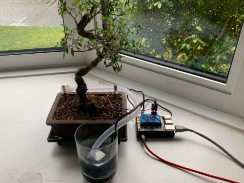
The irrigation PiHAT can be used for the irrigation of small gardens/vegetable patches via soil moisture level sensing and water dispensing. It may also be used in lab environments where scientists need to hold the moisture level of the soil at a constant level.
An optional configuration, which shows the modular ability of the HAT, is to replace the moisture sensors with a float switch or humidity sensor to either fill up pools; ponds; or water tanks or to operate ventilation systems if an enclosed space reaches a maximum humidity level.
The PiHAT will allow more advanced users to continuously perform measurements or monitor the soil moisture levels by sending its input from the sensors into the main Pi GPIO header.
How To Operate The...
Circuit Design Process
Final PCB Resources
Here's how to get started with your own Irrigation System PiHAT project!
Clone this repository to your computer to get started by using the following command line git command:
git clone https://github.com/ryxcam002/IrrigationPiHat
Change directory into the newly cloned repo using:
cd IrrigationPiHat
Make sure you have the latest version of KiCAD and LTSpice installed. The download links to these open source programs can be found at:
KiCAD - https://www.kicad.org/download/
LTSpice - https://www.analog.com/en/design-center/design-tools-and-calculators/ltspice-simulator.html
Go through the design files to check if all is working well. If you wish to make any changes to the design, pay particular attention to the Individual Module Schematics, Combined Schematic & PCB, and Simulation Files folders.
Individual Module Schematics folder is where you will find each submodule KiCAD schematic design. These can be modified individually to suit your needs.Simulation Files folder is where the V2.0 circuits weere simulated to determine if all parameters ffor circuit components were setup correctly.Combined Schematic & PCB folder is where all the submodules have been combined to form a single schematic, ready for PCB footprint assignment and BOM generation.Generate gerber files for final PCB manufacturing. To do this, open the .kicad_pcb file in the Combined Schematic & PCB folder, ensure that all components/PCB specifications are correct and generate the gerber files from there.
Manufacture PCB and solder all components or have this done by the manufacturer if they support this. You now have a micro irrrigation controller!
See the full contribution documentation here.
| Qty | Value | Footprint | References |
|---|---|---|---|
| 14 | 1K | Resistor_SMD:R_0201_0603Metric | R2, R4, R6, R7, R11, R12, R14, R15, R17, R19, R20, R29, R30, R31 |
| 10 | R_POT | Potentiometer_SMD:Potentiometer_Bourns_3314G_Vertical | RV1, RV2, RV3, RV4, RV5, RV6, RV7, RV8, RV9, RV10 |
| 7 | Conn_01x02_Male | Connector_PinHeader_1.00mm:PinHeader_1x02_P1.00mm_Vertical | J1, J2, J3, J5, J6, J7, J8 |
| 6 | 160 | Resistor_SMD:R_0201_0603Metric | R8, R9, R10, R21, R22, R23 |
| 5 | LMV324 | Package_SO:SOIC-14_3.9x8.7mm_P1.27mm | U1, U2, U3, U4, U6 |
| 4 | PN2222A | Package_TO_SOT_SMD:SOT-323_SC-70 | Q1, Q2, Q3, Q4 |
| 2 | 0.1µ | Capacitor_SMD:C_0201_0603Metric | C5, C6 |
| 2 | 10K | Resistor_SMD:R_0201_0603Metric | R1, R13 |
| 2 | 1k | Resistor_SMD:R_0201_0603Metric | R35, R36 |
| 2 | 2.5K | Resistor_SMD:R_0201_0603Metric | R5, R18 |
| 2 | 3636 | Resistor_SMD:R_0201_0603Metric | R3, R16 |
| 2 | 511k | Resistor_SMD:R_0201_0603Metric | R28, R33 |
| 2 | 74HC86 | Package_SO:SOIC-14_3.9x8.7mm_P1.27mm | U5, U7 |
| 2 | BSC082N10LSG | Package_TO_SOT_SMD:TDSON-8-1 | Q6, Q7 |
| 2 | Green LED | LED_SMD:LED_0201_0603Metric | D3, D6 |
| 2 | Orange LED | LED_SMD:LED_0201_0603Metric | D2, D5 |
| 2 | Red LED | LED_SMD:LED_0201_0603Metric | D1, D4 |
| 2 | SW_SPDT | Button_Switch_SMD:JS102011JCQN | SW1, SW2 |
| 1 | 0.01µ | Capacitor_SMD:C_0201_0603Metric | C1 |
| 1 | 150µ x3, Rser=0.1 | Capacitor_SMD:C_0201_0603Metric | C7 |
| 1 | 18.7k | Resistor_SMD:R_0201_0603Metric | R26 |
| 1 | 1Meg | Resistor_SMD:R_0201_0603Metric | R25 |
| 1 | 1n | Capacitor_SMD:C_0201_0603Metric | C2 |
| 1 | 30.1k | Resistor_SMD:R_0201_0603Metric | R27 |
| 1 | 33µ, Rser=15m | Inductor_SMD:L_1206_3216Metric | L1 |
| 1 | 36.5k | Resistor_SMD:R_0201_0603Metric | R32 |
| 1 | 4.7µ | Capacitor_SMD:C_0201_0603Metric | C4 |
| 1 | 6m | Resistor_SMD:R_0201_0603Metric | R34 |
| 1 | 75k | Resistor_SMD:R_0201_0603Metric | R24 |
| 1 | Cpar=100p,Rser=10k | Capacitor_SMD:C_0201_0603Metric | C3 |
| 1 | LMV321 | Package_TO_SOT_SMD:TSOT-23-5 | U10 |
| 1 | LTC3895IFE#TRPBF | LTC3895IFE#TRPBF:SOP50P640X120-39N | IC1 |
| 1 | Raspberry_Pi_2_3 | Module:Raspberry_Pi_Zero_Socketed_THT_FaceDown_MountingHoles | J4 |
| 1 | Si4482DY | Package_TO_SOT_SMD:TDSON-8-1 | Q5 |

JLJ-V14/Synchronous-Buck-converter
A synchronous buck converter project built from the ground up to practice power stage design, feedback control implementation, and real-time embedded firmware development.


DangerousPrototypes/BusPirate5-hardware
Bus Pirate Hardware and accessories for v5 and higher

brucemack/microlink
An open source EchoLink/AllStarLink implementation that runs on a simple microcontroller.


It measures 65.2 × 30.1 mm and has 6 copper layers, 1.6 mm thick.
86 parts, built around the LMV324, LMV321, LTC3895IFE#TRPBF and 74HC86D. The full list of its parts is on this page, with links to each part's symbol and footprint where PCBKit's library has them.
From the Cameron-Ray/IrrigationPiHat repository on GitHub, at the commit this page was made from: the board is Combined Schematic & PCB/Main Circuit.kicad_pcb. PCBKit opens the board in the browser, with nothing to install.
Its repository publishes it under the MIT licence: you may reuse it on that licence's terms (keep the author's notice, and for a copyleft licence share your changes alike).