






4 layers70 × 70 mm

 CNES/argos-demo-board7
Demo board designed to use the ARRIBADA SMD module via USB to send ARGOS messages to the Kineis constellation.
ARGOS DEMO is an open-source printed circuit board by CNES, from the CNES/argos-demo-board repository on GitHub, published under the CERN-OHL-S-2.0 licence. It is a 4-layer board of 50 × 80 mm with 91 parts on 87 nets, routed with 605 tracks and 252 vias.
It is built around the FT231XQ-R, 1206L035/16YR and B4B-XH-A, with the BSN20, SMAJ15CA and 3610213126S among its other parts. Its parts include 34 resistors, 16 capacitors, 9 diodes, 8 connectors and 6 ICs. It belongs with the home automation and IoT boards of this library.


Demonstration and evaluation board designed to operate the Arribada Argos SMD module via USB and transmit ARGOS uplink messages to the Kineis satellite constellation.
© 2025/2026 CNES – Paul Miailhe.
This material is licensed under the CERN Open Hardware Licence Version 2 (CERN-OHL-S).
See licence: https://ohwr.org/licences/
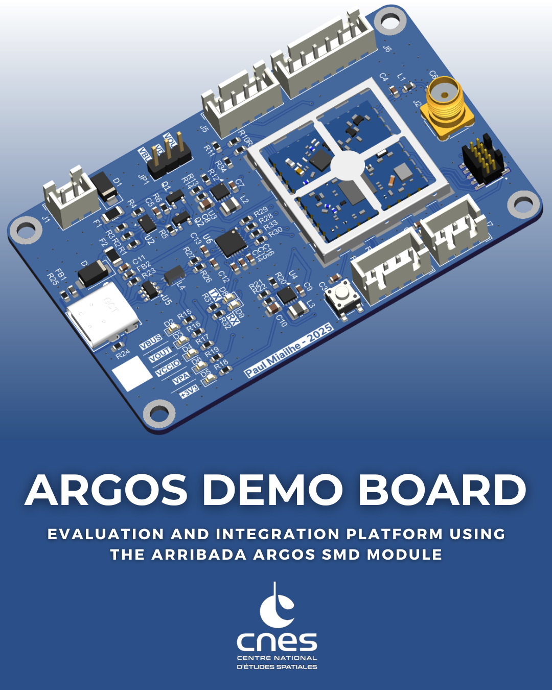
This project presents an Argos Transceiver Demonstration Board intended for the evaluation, validation, and operation of the Arribada Argos SMD module.
The board provides a compact and robust hardware platform to transmit ARGOS uplink messages to the Kineis satellite constellation using a standard USB interface.
Communication between the host computer and the Arribada SMD module is handled by a FTDI FT231XQ USB-to-UART bridge, directly interfacing with the module UART. This approach enables simple control of the transceiver using standard serial terminals or custom software tools.
The demonstration board integrates all essential functions required to operate the Arribada SMD module in a laboratory or development environment, including power supply conditioning, USB-to-UART communication, and RF interfacing. It is primarily intended to support early hardware validation, firmware development, and system-level testing of Argos communication chains prior to integration into a final embedded or avionics system.
This board targets engineers, students, and developers involved in satellite communications, avionics, IoT, or space-related applications, and may be used both as a standalone evaluation platform and as a reference hardware design.
Inline with Arribada's open source philosophy, this board deliberately adopts a design distinct from the official demonstration hardware, focusing on simplicity and direct plug-and-play operation from a standard PC. The schematic and architecture are provided for reference, allowing potential users to reuse, adapt, or extend them according to their own needs..
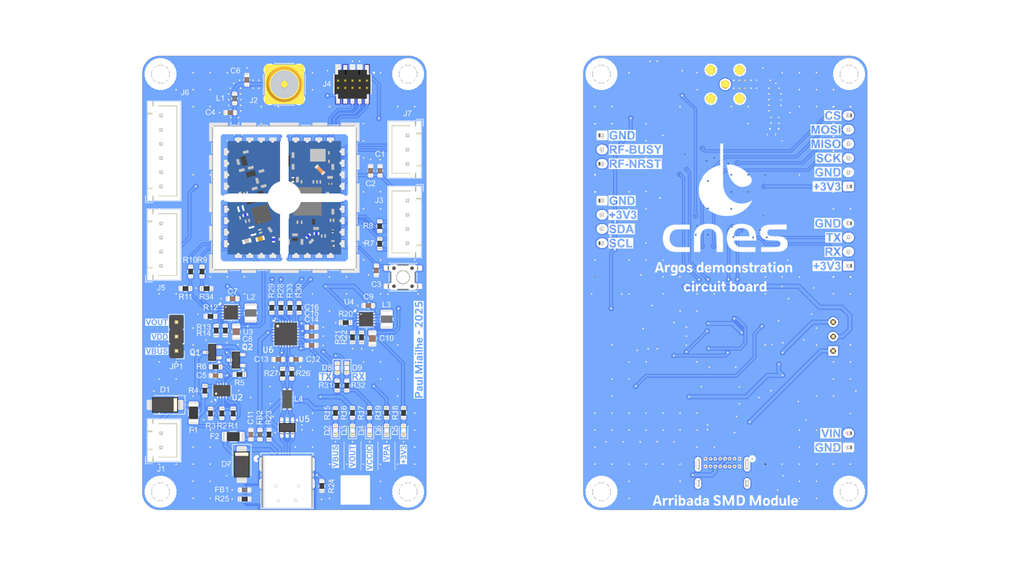
Communication between the host PC and the Arribada Argos SMD module is performed through the module’s UART interface.
This interface is used to send AT commands from a PC in order to configure the module and transmit ARGOS uplink messages.
→ See details on GitHub Arribada
The USB-to-UART conversion is handled by a FTDI FT231XQ USB 2.0 to UART bridge. This device converts USB data received from a virtual COM port into UART signals fully compatible with the Arribada SMD module.
This architecture allows the board to be operated using:
No additional embedded controller is required, which simplifies early testing and debugging.
The card supports two power supply modes to suit different uses.
Power source selection is performed using the JP1 jumper, which allows switching between:
The external power input on connector J1 is protected by:
The LTC4365 provides:
After the protection stage, the power rail is distributed to two TPS63900 buck-boost converters:
The Argos Demo Board uses the following connector families:
USB4085-GF-A (GCT)
USB Type-C receptacle (16-pin) used for:
JST B2B-XH series
Through-hole wire-to-board connectors used for:
FTSH-105-01-L-DV-K (Samtec)
10-pin JTAG connector used for:
60312002114503 (Würth Elektronik)
SMA 50 Ω RF connector used for:
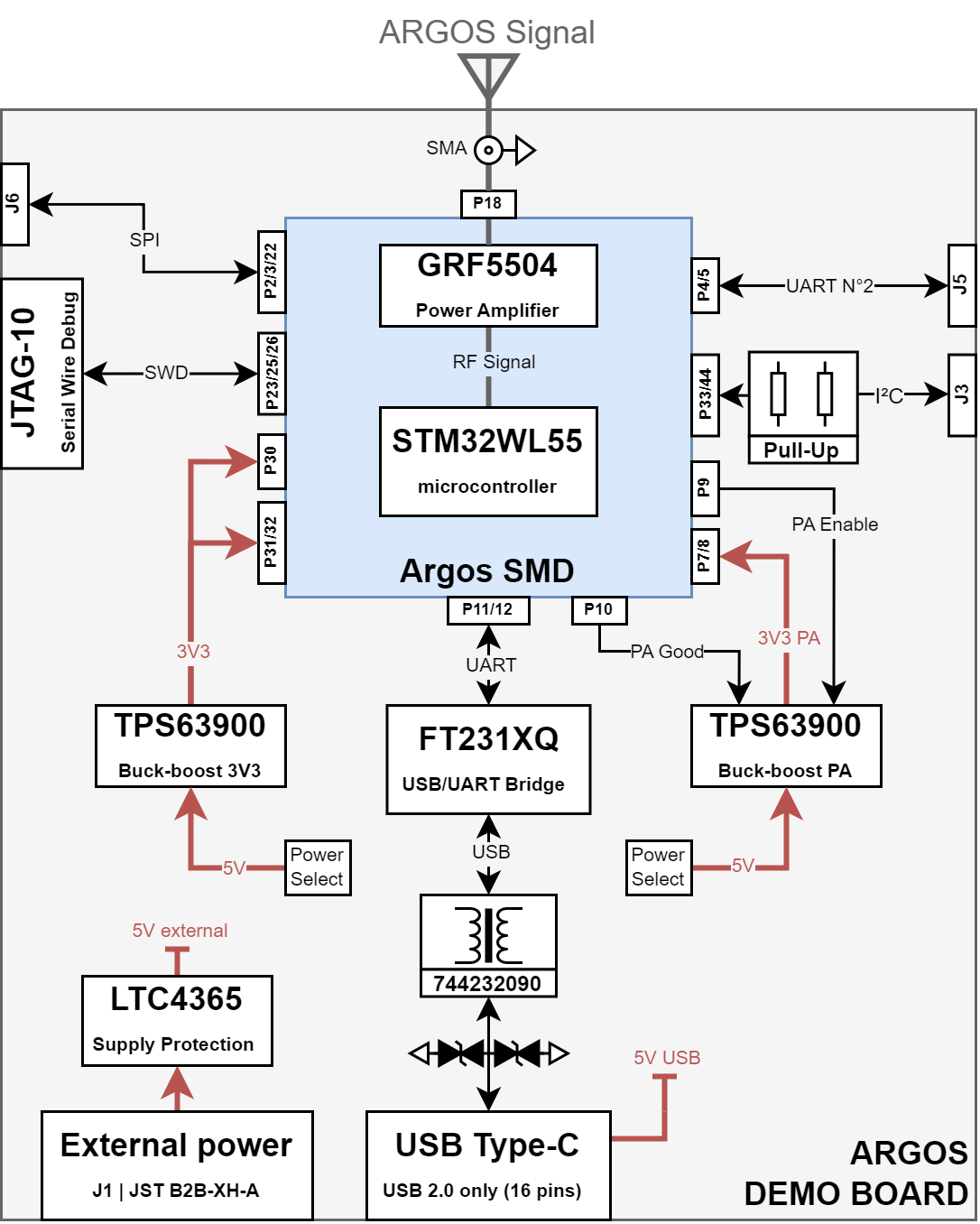
Components used on the board, with their official datasheets:
| Reference | Part Number | Role / Function | Datasheet |
|---|---|---|---|
| D1, D7 | SMAJ15CA | TVS diode for surge and ESD protection | → Datasheet Littelfuse |
| F1, F2 | 1206L035/16YR | Resettable PTC fuse (overcurrent protection) | → Datasheet Littelfuse |
| FB1, FB2 | BLM18KG601SN1D | Ferrite bead for EMI suppression | → Datasheet Murata |
| L4 | 744232090 | Common-mode choke for USB line filtering | → Datasheet Würth Elektronik |
| Q1, Q2 | BSN20 | N-channel MOSFET for switching and protection | → Datasheet DIODES INC. |
| SW1 | PTS647 | Momentary tactile push button switch | → Datasheet C&K |
| U2 | LTC4365DDB | Overvoltage, undervoltage and reverse polarity protection IC | → Datasheet Analog Devices |
| U3, U4 | TPS63900 | Buck-boost DC/DC converters | → Datasheet Texas Instruments |
| U5 | 82400102 | Low-capacitance TVS diode array for USB protection | → Datasheet Würth Elektronik |
| U6 | FT231XQ | USB-to-UART bridge | → Datasheet FTDI |
| H4 | 3610213126S | RF shielding cabinet | → Datasheet Würth Elektronik |
| J8 | USB4085-GF-A | USB 2.0-only 16P Type-C Receptacle connector | → Datasheet GCT |
| J2 | 60312002114503 | Coaxial connector SMA | → Datasheet Würth Elektronik |
| J4 | FTSH-105-01-L-DV-K | JTAG 10-PINS | → Datasheet Samtec |
| J1, J3, J5, J6, J7 | B2B-XH | Through-hole wire-to-board connectors | → Datasheet JST |
| U1 | Argos SMD module | Transceiver Argos SMD for uplink Argos satellite | → Datasheet Arribada |
Refer to the Arribada SMD module documentation for command syntax and operational details.
ARGOS transmissions are subject to regulatory constraints and operational authorization.
ARGOS transmissions are subject to regulatory and operational constraints.
Arribada Initiative – Official site
See link: https://arribada.org
Official Argos SMD Arduino Demo – by Arribada
The full Arduino-based demonstration for the Argos SMD module is available on GitHub.
See link: https://github.com/arribada/argos-smd-test-arduino
Official Breakout Board FeatherWings – by Arribada
This breakout board can be used with a Feather board (from Adafruit) to connect the ARGOS-SMD module.
It exposes the ARGOS-SMD module pins to the Feather board and includes a dedicated LDO to power the RF amplifier.
See link: https://github.com/arribada/featherwings-argos-smd-hw
Official Argos SMD Hardware Module – by Arribada
The Arribada Argos SMD module is a compact 20 × 20 mm PCB designed to operate as a standalone module or co-processor, enabling satellite communication via the Kineis network.
See link: https://github.com/arribada/argos-smd-hw
| Qty | Value | Footprint | References |
|---|---|---|---|
| 8 | 0R | Resistor_SMD:R_0603_1608Metric | R5, R6, R9, R10, R13, R14, R21, R22 |
| 7 | LED_Small | LED_SMD:LED_0603_1608Metric | D2, D3, D4, D5, D6, D8, D9 |
| 5 | 100nF | Capacitor_SMD:C_0603_1608Metric | C1, C3, C5, C14, C15 |
| 5 | 270R | Resistor_SMD:R_0603_1608Metric | R17, R18, R19, R31, R32 |
| 4 | 10R | Resistor_SMD:R_0603_1608Metric | R28, R29, R30, R33 |
| 4 | M3 | MountingHole:MountingHole_3.2mm_M3_DIN965_Pad | H1, H2, H3, H5 |
| 2 | 10K | Resistor_SMD:R_0603_1608Metric | R7, R8 |
| 2 | 10k | Resistor_SMD:R_0603_1608Metric | R11, R34 |
| 2 | 10uF | Capacitor_SMD:C_0603_1608Metric | C7, C9 |
| 2 | 1206L035/16YR | Fuse:Fuse_1206_3216Metric | F1, F2 |
| 2 | 2.2uH | Inductor_SMD:L_1008_2520Metric | L2, L3 |
| 2 | 22uF | Capacitor_SMD:C_0805_2012Metric | C8, C10 |
| 2 | 27R | Resistor_SMD:R_0603_1608Metric | R26, R27 |
| 2 | 36.5K | Resistor_SMD:R_0603_1608Metric | R12, R20 |
| 2 | 4.7uF | Capacitor_SMD:C_0603_1608Metric | C2, C16 |
| 2 | 470R | Resistor_SMD:R_0603_1608Metric | R15, R16 |
| 2 | 47pF | Capacitor_SMD:C_0603_1608Metric | C12, C13 |
| 2 | 5.1K | Resistor_SMD:R_0603_1608Metric | R23, R24 |
| 2 | B4B-XH-A | Connector_JST:JST_XH_B4B-XH-A_1x04_P2.50mm_Vertical | J3, J5 |
| 2 | BLM18KG601SN1D | Inductor_SMD:L_0603_1608Metric | FB1, FB2 |
| 2 | BSN20 | Package_TO_SOT_SMD:SOT-23 | Q1, Q2 |
| 2 | SMAJ15CA | Diode_SMD:D_SMA | D1, D7 |
| 2 | TPS63900 | Package_SON:WSON-10-1EP_2.5x2.5mm_P0.5mm_EP1.2x2mm | U3, U4 |
| 1 | 1.2M | Resistor_SMD:R_0603_1608Metric | R1 |
| 1 | 100k | Resistor_SMD:R_0603_1608Metric | R4 |
| 1 | 10nF | Capacitor_SMD:C_0603_1608Metric | C11 |
| 1 | 150K | Resistor_SMD:R_0603_1608Metric | R2 |
| 1 | 150k | Resistor_SMD:R_0603_1608Metric | R3 |
| 1 | 18nH | Inductor_SMD:L_0603_1608Metric | L1 |
| 1 | 3.6pF | Capacitor_SMD:C_0603_1608Metric | C4 |
| 1 | 3610213126S | Project_library:H_Wurth_WE-SHC-SMT-FRAME_36103255S | H4 |
| 1 | 42375-1246 | Connector_PinHeader_2.54mm:PinHeader_1x03_P2.54mm_Vertical | JP1 |
| 1 | 60312002114503 | Connector_Coaxial:SMA_Wurth_60312002114503_Vertical | J2 |
| 1 | 744232090 | Inductor_SMD:L_CommonMode_Wurth_WE-CNSW-1206 | L4 |
| 1 | 82400102 | Package_TO_SOT_SMD:SOT-23-6 | U5 |
| 1 | Argos SMD module | Project_library:SMD ARGOS | U1 |
| 1 | B2B-XH-A | Connector_JST:JST_XH_B2B-XH-A_1x02_P2.50mm_Vertical | J1 |
| 1 | B3B-XH-A | Connector_JST:JST_XH_B3B-XH-A_1x03_P2.50mm_Vertical | J7 |
| 1 | B6B-XH-A | Connector_JST:JST_XH_B6B-XH-A_1x06_P2.50mm_Vertical | J6 |
| 1 | FT231XQ | Package_DFN_QFN:QFN-20-1EP_4x4mm_P0.5mm_EP2.5x2.5mm | U6 |
| 1 | JTAG 10-PINS | Project_library:SAMTEC_FTSH-105-XX-X-DV | J4 |
| 1 | LOGO | LOGO | G*** |
| 1 | LTC4365DDB | Package_DFN_QFN:DFN-8-1EP_2x3mm_P0.5mm_EP0.61x2.2mm | U2 |
| 1 | NC | Resistor_SMD:R_0603_1608Metric | R25 |
| 1 | NC | Capacitor_SMD:C_0603_1608Metric | C6 |
| 1 | PTS647 | Button_Switch_SMD:SW_SPST_PTS647_Sx38 | SW1 |
| 1 | USB4085-GF-A | Project_library:CONN16_USB4085-GF-A_GCT | J8 |

themarcolab/Stardrive-Shield
With STARDRIVE SHIELD you can implement from 6 step to FOC motor control algorithms.

gustebeast/public-steel-guitar
A pedal steel guitar you can build yourself, from parts anyone can buy.

01binary/str1ker
A human-scale mech integrated with Robot Operating System


CUSail-Navigation/PCB-FA25-SP26
This is a repository containing the PCBs designed during the FA25-SP26 academic year. Due to high compatibility and relative ease of use, all of these files are made with KiCad.

Luca-Jones/enph-253-pet-rescue
The mechanical design was done with Onshape as our CAD tool. It is simple to use and allows for collaboration and version control.
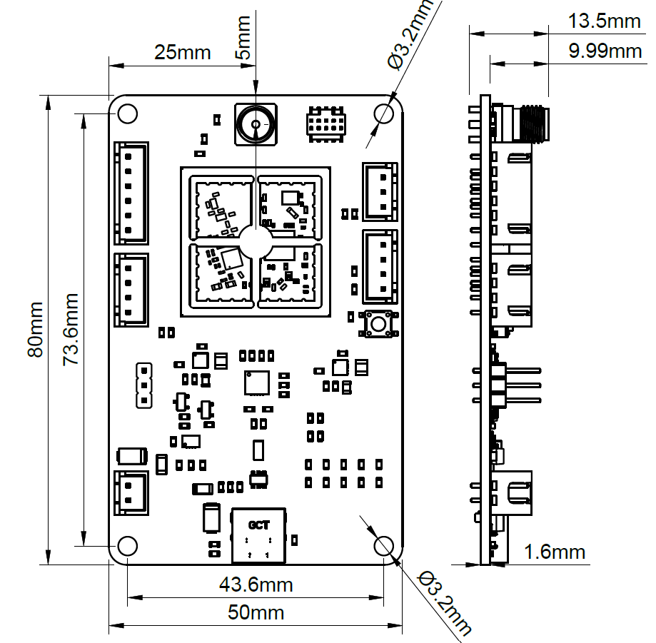
It measures 50 × 80 mm and has 4 copper layers, 1.62 mm thick.
91 parts, built around the FT231XQ-R, 1206L035/16YR, B4B-XH-A and BSN20. The full list of its parts is on this page, with links to each part's symbol and footprint where PCBKit's library has them.
From the CNES/argos-demo-board repository on GitHub, at the commit this page was made from: the board is ARGOS DEMO.kicad_pcb and its schematic ARGOS DEMO.kicad_sch. PCBKit opens the board in the browser, with nothing to install.
Its repository publishes it under the CERN-OHL-S-2.0 licence: you may reuse it on that licence's terms (keep the author's notice, and for a copyleft licence share your changes alike).