2 layers64 × 50 mm
Resol VBus RevE
labodj/resol-vbus-interface
Isolated RESOL VBus RX/TX interface for ESPHome: KiCad Rev E prototype, BOM and fabrication files
51 parts

 C12isme945/BioSmartSense-IoT
Portable IoT Electrochemical Biosensor & Edge AI Platform for Real-Time Water Quality & Bio-Diagnostics (Hyperbloom September Hackathon 2026)
AD5940 Lab is an open-source printed circuit board by C12isme945, from the C12isme945/BioSmartSense-IoT repository on GitHub. It is a 4-layer board of 60 × 60 mm with 71 parts on 64 nets, routed with 535 tracks and 65 vias.
It is built around the AD5940BCBZ-RL7, ADP150AUJZ-3.3-R7 and MAX809TEUR+T, with the SS14 among its other parts. Its parts include 26 capacitors, 14 resistors, 7 connectors, 4 ICs and 2 diodes.







Decentralized Point-of-Care Environmental Water Testing & Smart Biomaterial Analytics
Submitted to Hyperbloom September Hackathon 2026 (IoT + Machine Learning/AI + Social Good Track)
Water pollution, heavy metal toxicity (Lead $Pb^{2+}$, Cadmium $Cd^{2+}$), and delayed physiological biomarker diagnostics disproportionately impact vulnerable populations. Traditional laboratory electrochemical workstations (potentiostats / impedance analyzers) cost upwards of $5,000–$15,000 USD, requiring bulky benchtop setups and trained operators.
BioSmartSense-IoT bridges this gap:
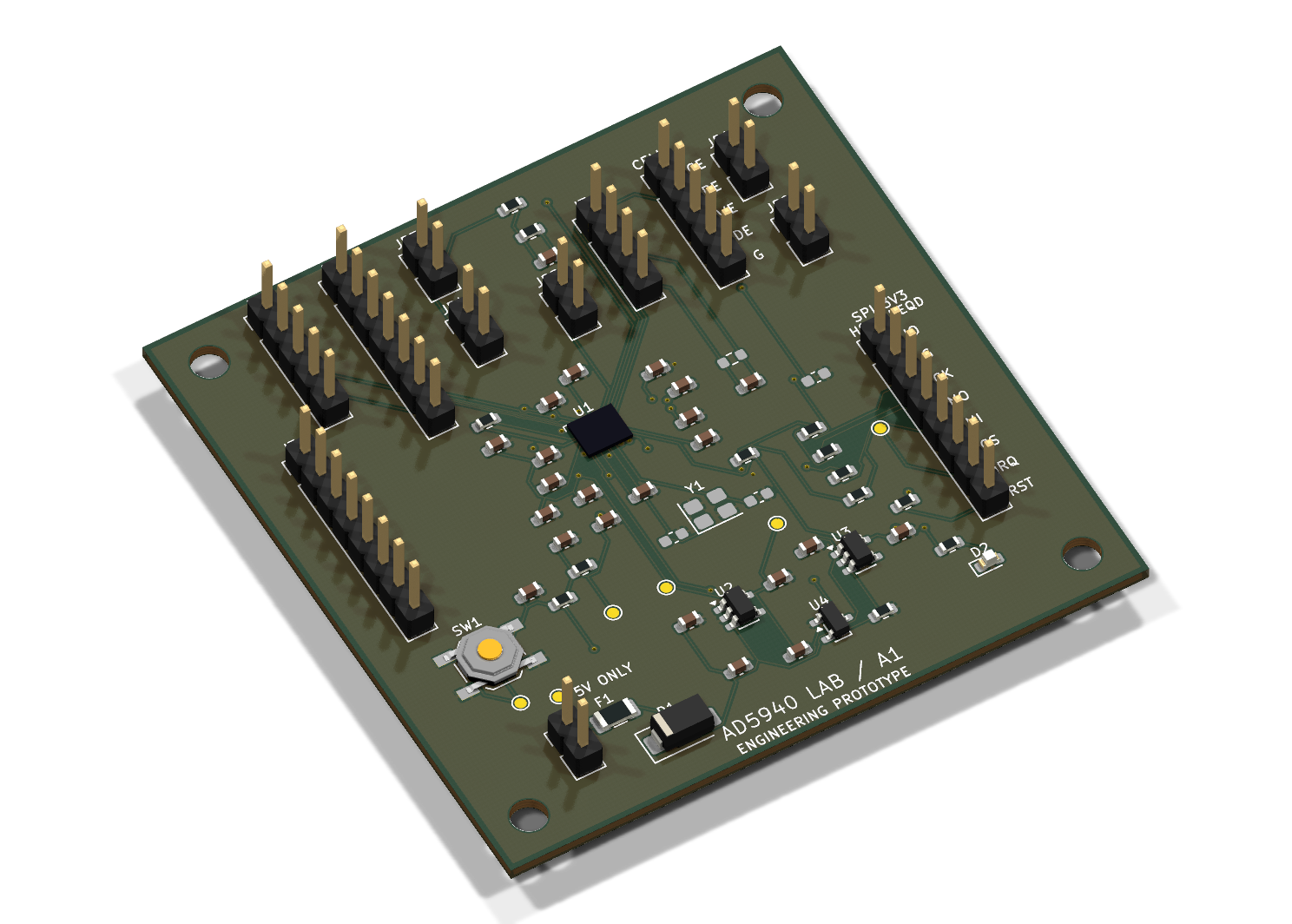
Figure 1: Raytraced 3D render of the BioSmartSense-IoT 4-layer HDI board featuring the AD5940 AFE, precision analog LDOs, and standard gold-plated SPE card-edge connector.
| Subsystem | Specification |
|---|---|
| Main Analog Front End (AFE) | Analog Devices AD5940 (16-Bit, 800 kSPS SAR ADC, On-chip DFT engine) |
| PCB Stackup | 4-Layer FR4 HDI ($1.2\text{ mm}$ thickness, controlled impedance, JLCPCB standard) |
| Sensor Interface | Standard 3-Electrode Screen Printed Electrode (SPE: WE, RE, CE, 2.54mm pitch) |
| Frequency Range | $0.016\text{ Hz}$ to $200\text{ kHz}$ (Electrochemical Impedance Spectroscopy) |
| Current Dynamic Range | $\pm 28\text{ }\mu\text{A}$ up to $\pm 3\text{ mA}$ with programmable internal RTIAs |
| Host Interface | High-speed SPI ($16\text{ MHz}$) / USB-UART telemetry |
| Total BOM Cost | $34.80 USD per small-batch prototype |
graph TD
    subgraph S1["Physical Layer (IoT Hardware)"]
        SPE["Screen Printed Electrode (SPE)<br/>WE / RE / CE"] --> AFE["AD5940 Precision AFE<br/>(16-bit ADC + DFT Accelerator)"]
        AFE --> MCU["Microcontroller / Edge Host<br/>(SPI Driver & Register Sequencer)"]
    end

    subgraph S2["Machine Learning & Signal Core"]
        MCU --> FeatureEng["Electrochemical Signal Processing<br/>(Randles Fitting: Rs, Rct, Cdl, Warburg)"]
        FeatureEng --> Classifier["Analyte ML Classifier<br/>(Heavy Metal Quantification & WQI)"]
    end

    subgraph S3["User Telemetry & Action"]
        Classifier --> Dash["Streamlit Telemetry Dashboard<br/>(Nyquist / Bode / CV Plots)"]
        Classifier --> Alert["WHO / EPA Safety Risk Alert<br/>(Safe / Warning / Hazardous)"]
end# Clone the repository
git clone https://github.com/C12isme945/BioSmartSense-IoT.git
cd BioSmartSense-IoT
# Install Python dependencies
pip install -r requirements.txtpython -m unittest discover -s tests -v(Runs 3 test suites verifying Randles extraction, water quality classification, and CV analysis in <0.3s)
streamlit run dashboard/app.pyOpen your browser at http://localhost:8501 to test live Nyquist/Bode plots, switch sample presets, and inspect the 4-layer PCB engineering views.
# Run real-time diagnostic scan
python cli.py --analyte "Lead (Pb2+)" --rct 850.0

# Export JSON for IoT telemetry pipelines
python cli.py --analyte "Cadmium (Cd2+)" --jsonBioSmartSense-IoT/
├── README.md # Master documentation & benchmark guide
├── LICENSE # Apache 2.0 Open-Source License
├── requirements.txt # Pinned Python package dependencies
├── .gitignore # Git ignore rules for KiCad and Python
├── cli.py # Command-line interface for edge deployment
├── dashboard/
│ └── app.py # Streamlit live telemetry dashboard
├── ml_core/
│ ├── feature_extraction.py # Randles circuit parameter extraction & CV peaks
│ ├── analyte_classifier.py # Heavy metal & Water Quality Index (WQI) models
│ └── simulation_data.py # Multi-frequency EIS & CV benchmark generator
├── firmware/
│ └── ad5940_driver.py # AD5940 SensorPal SPI driver interface
├── hardware/ # Complete KiCad 8 Hardware Design
│ ├── design/ # KiCad schematic, PCB, and symbol libraries
│ ├── exports/ # Schematics PDF, 3D renders, layer drawings
│ ├── JLC_PCB_UPLOAD/ # Ready-to-order JLCPCB Gerbers, drill files, BOM
│ ├── AD5940_Lab_A1_Engineering.zip
│ └── 电气设计与首板调试.md # Hardware debugging and layout guidelines
├── docs/
│ └── images/ # High-resolution renders and block diagrams
└── tests/
└── test_biosmartsense.py # Comprehensive unit testshttps://biosmartsense.streamlit.app| Qty | Value | Footprint | References |
|---|---|---|---|
| 9 | 100nF | Capacitor_SMD:C_0603_1608Metric | C1, C2, C4, C6, C13, C14, C15, C25, C27 |
| 5 | 33R | Resistor_SMD:R_0603_1608Metric | R5, R6, R7, R8, R9 |
| 4 | 470nF | Capacitor_SMD:C_0603_1608Metric | C9, C10, C11, C12 |
| 4 | M3 | MountingHole:MountingHole_3.2mm_M3 | H1, H2, H3, H4 |
| 3 | 10uF | Capacitor_SMD:C_0603_1608Metric | C3, C5, C20 |
| 3 | 1uF | Capacitor_SMD:C_0603_1608Metric | C7, C21, C23 |
| 3 | 4.7uF | Capacitor_SMD:C_0603_1608Metric | C8, C22, C24 |
| 2 | 10k | Resistor_SMD:R_0603_1608Metric | R10, R11 |
| 2 | 6.8pF C0G | Capacitor_SMD:C_0603_1608Metric | C18, C19 |
| 2 | ADP150AUJZ-3.3-R7 | Package_TO_SOT_SMD:SOT-23-5 | U2, U3 |
| 1 | 100k | Resistor_SMD:R_0603_1608Metric | R14 |
| 1 | 100k 0.1% | Resistor_SMD:R_0603_1608Metric | R3 |
| 1 | 100nF 5% | Capacitor_SMD:C_0603_1608Metric | C26 |
| 1 | 10k 0.1% | Resistor_SMD:R_0603_1608Metric | R13 |
| 1 | 10k 0.1% 10ppm | Resistor_SMD:R_0603_1608Metric | R2 |
| 1 | 16MHz CL=8pF OPTION | Crystal:Crystal_SMD_3225-4Pin_3.2x2.5mm | Y1 |
| 1 | 1k | Resistor_SMD:R_0603_1608Metric | R1 |
| 1 | 1k 0.1% | Resistor_SMD:R_0603_1608Metric | R12 |
| 1 | 2-WIRE SHORT CE-RE | Connector_PinHeader_2.54mm:PinHeader_1x02_P2.54mm_Vertical | JP1 |
| 1 | 2.2k | Resistor_SMD:R_0603_1608Metric | R4 |
| 1 | 220nF | Capacitor_SMD:C_0603_1608Metric | C17 |
| 1 | 3V3 SPI HOST | Connector_PinHeader_2.54mm:PinHeader_1x08_P2.54mm_Vertical | J2 |
| 1 | 5V INPUT 4.75-5.25V | Connector_PinHeader_2.54mm:PinHeader_1x02_P2.54mm_Vertical | J1 |
| 1 | AD5940BCBZ-RL7 | AD5940_Lab:AD5940_WLCSP56_0.4mm | U1 |
| 1 | ADC EXPANSION | Connector_PinHeader_2.54mm:PinHeader_1x07_P2.54mm_Vertical | J5 |
| 1 | AFE EXPANSION | Connector_PinHeader_2.54mm:PinHeader_1x05_P2.54mm_Vertical | J4 |
| 1 | AVDD | TestPoint:TestPoint_Pad_D1.0mm | TP2 |
| 1 | CELL CE RE WE DE GND | Connector_PinHeader_2.54mm:PinHeader_1x05_P2.54mm_Vertical | J6 |
| 1 | DUMMY CE | Connector_PinHeader_2.54mm:PinHeader_1x02_P2.54mm_Vertical | JP3 |
| 1 | DUMMY RE | Connector_PinHeader_2.54mm:PinHeader_1x02_P2.54mm_Vertical | JP4 |
| 1 | DUMMY WE | Connector_PinHeader_2.54mm:PinHeader_1x02_P2.54mm_Vertical | JP5 |
| 1 | DVDD | TestPoint:TestPoint_Pad_D1.0mm | TP3 |
| 1 | EXTERNAL TIA | Connector_PinHeader_2.54mm:PinHeader_1x04_P2.54mm_Vertical | J7 |
| 1 | GND | TestPoint:TestPoint_Pad_D1.0mm | TP1 |
| 1 | GPIO EXPANSION | Connector_PinHeader_2.54mm:PinHeader_1x08_P2.54mm_Vertical | J3 |
| 1 | GPIO0 | TestPoint:TestPoint_Pad_D1.0mm | TP6 |
| 1 | GREEN | LED_SMD:LED_0603_1608Metric | D2 |
| 1 | IOVDD | TestPoint:TestPoint_Pad_D1.0mm | TP4 |
| 1 | MAX809TEUR+T | Package_TO_SOT_SMD:SOT-23 | U4 |
| 1 | PTC 100mA | Fuse:Fuse_1206_3216Metric | F1 |
| 1 | RESET | Button_Switch_SMD:SW_SPST_TL3342 | SW1 |
| 1 | RESET_N | TestPoint:TestPoint_Pad_D1.0mm | TP5 |
| 1 | SHORT WE-DE IF MODE REQUIRES | Connector_PinHeader_2.54mm:PinHeader_1x02_P2.54mm_Vertical | JP2 |
| 1 | SS14 | Diode_SMD:D_SMA | D1 |
labodj/resol-vbus-interface
Isolated RESOL VBus RX/TX interface for ESPHome: KiCad Rev E prototype, BOM and fabrication files

marian1911/Proyecto-CUBESAT-TRANSPODER-VHF-UHF
En este repositorio se guardan todos los archivos de desarrollo referidos a el diseño y fabricacion del trasnponder VHF/UHF


Kevpamm/PCB-PLL-ADF4159
This git repository tracks the design and development of the PCB for a phase-locked loop (PLL) system centered around the ADF4159 IC


Pgr18/CELL_Z_SPECT_hardware
Печатные платы для проекта клеточной импедансной спектроскопии

It measures 60 × 60 mm and has 4 copper layers, 1.2 mm thick.
71 parts, built around the AD5940BCBZ-RL7, ADP150AUJZ-3.3-R7, MAX809TEUR+T and SS14. The full list of its parts is on this page, with links to each part's symbol and footprint where PCBKit's library has them.
From the C12isme945/BioSmartSense-IoT repository on GitHub, at the commit this page was made from: the board is hardware/design/AD5940_Lab.kicad_pcb and its schematic hardware/design/02_Power.kicad_sch. PCBKit opens the board in the browser, with nothing to install.
Its repository states no licence, so its author keeps all rights: ask C12isme945 before reusing the design.