
2 layers64 × 46 mm

 Brillar0101/NeuralCard
A credit-card-sized PCB that runs a neural network: ESP32-S3, 6-axis IMU, and 24 LEDs wired as the network itself. Draw a digit in the air and watch the activations light up
NeuralCard is an open-source printed circuit board by Brillar0101, from the Brillar0101/NeuralCard repository on GitHub, published under the CERN-OHL-P-2.0 licence. It is a 2-layer board of 85.6 × 54 mm with 72 parts on 63 nets, routed with 939 tracks and 56 vias.
It is built around the MCP73831T-2ACI/OT-HXY, ME6211C33M5G-N and USBLC6-2SC6, with the AO3401A, B5819W and TYPE-C-31-M-12 among its other parts. Its parts include 25 diodes, 15 resistors, 14 capacitors, 6 ICs and 3 switches. It belongs with the ESP32 boards of this library.





A business card that runs a neural network.
This is the sponsorship build, a fork of NeuralCard prepared for assembly by PCBWay. The BOM has been rewritten from JLCPCB and LCSC part codes into manufacturer part numbers PCBWay can quote, with approved alternates where a swap is safe and do-not-substitute rules where it is not. Every part in the schematic and the board now carries
Alt MPN,Alt Mfr, andSourcingfields alongside the existing MPN. Seedocs/SOURCING.mdfor the reasoning andfab/BOM_PCBWay.csvfor the order-ready BOM. No copper changed, and DRC and ERC still pass clean.
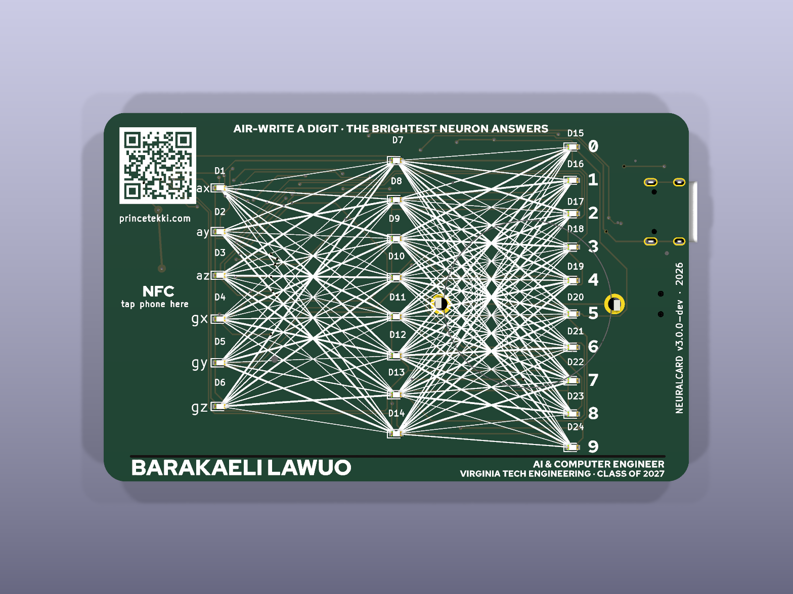
It is a credit-card-sized PCB, 85.6 by 54 mm, carrying an ESP32-S3, a 6-axis IMU, and 24 LEDs laid out as the network it actually runs: 6 input neurons, 8 hidden, 10 output. You hold the card, draw a digit in the air, and the LEDs light with the real activations as inference runs. Brightest output neuron wins.
The front artwork is the network diagram. The synapse lines are drawn at three stroke weights, the way a trained model's weights differ. There is also an NFC tag with a coil antenna etched into the copper, so tapping a phone opens princetekki.com/card and offers a vCard. That works with a dead battery, or no battery at all, because the phone's own field powers the tag.
| Path | What's in it |
|---|---|
hardware/ | KiCad 10 project: schematic, board, custom symbol and footprint libraries, 3D models |
fab/ | Manufacturing outputs: gerber zip, drill files, pick-and-place, and two BOMs: BOM_PCBWay.csv (MPN-based, for this build) and BOM_JLCPCB.csv (upstream, LCSC codes) |
firmware/ | ESP-IDF project. Charlieplex driver, IMU driver, gesture recorder. Builds today. |
docs/ | Design rationale, component sourcing, datasheet findings, DRC history, audits, FAQ |
render/ | The board renders used above |
CHANGELOG.md | Revision history, newest first |
Start with docs/DESIGN.md for why the board is shaped the
way it is, docs/FAQ.md for the questions people actually ask,
and docs/drc/README.md for the verification trail.
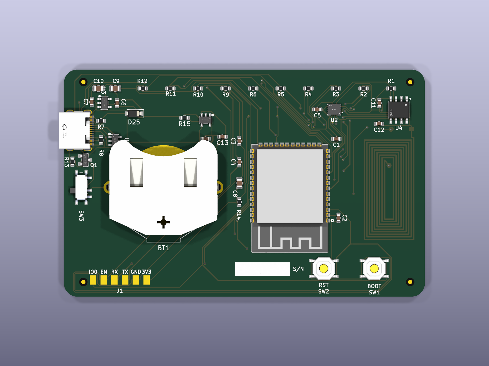
An ESP32-S3-WROOM-1-N8R2 does the thinking and runs the inference. An LSM6DS3TR-C accelerometer and gyro sits on I2C, and its six axes map one to one onto the six input neurons. The 24 red LEDs are charlieplexed across 6 GPIO with software PWM for the glow.
For the business-card half there is an ST25DV04K dynamic NFC tag with a 9-turn coil in the copper, tuned by a single external cap (C12) against the chip's internal capacitance.
USB-C arrived in v2.3. The S3 has native USB, so a plain cable flashes the board and gives a serial console without an adapter. A USBLC6-2SC6 protects the data pair.
Power comes from either a CR2032 through a real slide switch (SW3) or USB 5 V through an ME6211 LDO. A P-FET (Q1) disconnects the cell whenever USB is present, so the board can never try to charge a cell that is not rechargeable.
Two layers, ground poured on both sides and stitched. Every net is one connected cluster.
Power first. Two sources that can never fight each other.
flowchart LR
    USB["USB-C · J2<br/>5 V VBUS"] --> LDO["U3 · ME6211<br/>3.3 V LDO"]
    BT1["BT1<br/>CR2032 · 3.0 V"] -->|VBAT| SW3{{"SW3 · MSK12C02<br/>SPDT slide"}}
    SW3 -->|"ON"| Q1{{"Q1 · AO3401A<br/>P-FET isolation"}}
    SW3 -.->|"OFF"| NC(["open throw"])
    LDO --> RAIL[["+3V3 rail"]]
    LDO -.->|"VBUS present<br/>gates the cell off"| Q1
    Q1 --> RAIL
    RAIL --> U1["ESP32-S3"]
    RAIL --> U2["LSM6DS3TR-C"]
    RAIL --> U4["ST25DV04K"]
    RAIL --> LEDS["24 LEDs<br/>charlieplexed"]

    classDef src fill:#F0AB00,stroke:#795600,color:#151515
    classDef sw fill:#0066CC,stroke:#003366,color:#FFFFFF
    classDef rail fill:#009596,stroke:#005F60,color:#FFFFFF
    classDef load fill:#F0F0F0,stroke:#8A8D90,color:#151515
    classDef off fill:#FFFFFF,stroke:#C9190B,color:#C9190B,stroke-dasharray:4 3
    class USB,BT1 src
    class SW3,Q1,LDO sw
    class RAIL rail
    class U1,U2,U4,LEDS load
    class NC off
Then data. USB-C carries both power and programming. NFC is independent of both and needs no power of its own.
flowchart LR
    HOST(["laptop"]) -->|"USB-C · D+/D-"| ESD["U5 · USBLC6<br/>ESD array"]
    ESD -->|"native USB-Serial-JTAG"| U1["ESP32-S3"]
    U1 <-->|I2C| U2["IMU"]
    U1 <-->|I2C| U4["NFC tag"]
    U2 -.->|"motion interrupt"| U1
    U4 -.->|"field-detect GPO"| U1
    PHONE(["phone"]) -.->|"13.56 MHz field<br/>powers the tag"| U4
    U1 --> LEDS["24 LEDs"]

    classDef ext fill:#F0AB00,stroke:#795600,color:#151515
    classDef chip fill:#0066CC,stroke:#003366,color:#FFFFFF
    classDef out fill:#3E8635,stroke:#1F4D19,color:#FFFFFF
    class HOST,PHONE ext
    class ESD,U1,U2,U4 chip
    class LEDS out
And inference. The six IMU axes feed the six input neurons, and the LEDs at each node light with the real activations as the network runs.
flowchart LR
    IMU["LSM6DS3TR-C<br/>ax ay az · gx gy gz"] --> IN["INPUT<br/><b>6 neurons</b>"]
    IN --> HID["HIDDEN<br/><b>8 neurons</b>"]
    HID --> OUT["OUTPUT<br/><b>10 neurons</b><br/>digits 0-9"]
    OUT --> GUESS(["brightest neuron<br/>= the guess"])

    classDef sensor fill:#F0AB00,stroke:#795600,color:#151515
    classDef layer fill:#0066CC,stroke:#003366,color:#FFFFFF
    classDef out fill:#5752D1,stroke:#2A265F,color:#FFFFFF
    classDef result fill:#3E8635,stroke:#1F4D19,color:#FFFFFF
    class IMU sensor
    class IN,HID layer
    class OUT out
    class GUESS result
All 24 LEDs run from 6 GPIO by charlieplexing. That is why there are 6 current-limiting resistors rather than 24, and why the display works on a coin cell at all: only one LED is ever actually lit.
firmware/ is an ESP-IDF project that builds today. It has the charlieplex
driver, with the LED-to-pin mapping extracted from the board netlist rather
than guessed, the LSM6DS3 driver, and a motion-triggered gesture recorder that
prints labelled CSV over the USB-C console. That recorder is how you build a
training set.
cd firmware && idf.py set-target esp32s3 && idf.py build && idf.py flash monitorThe neural network itself is deliberately not in the repo yet: it has to be
trained on gestures recorded from real hands, which needs assembled boards.
See firmware/README.md.
Everything a fab needs is in fab/: NeuralCard_gerbers.zip (gerbers +
drill), NeuralCard-cpl.csv (placements), and a BOM. Use
BOM_PCBWay.csv for this build, which carries manufacturer part numbers,
approved alternates, and per-line substitution rules. BOM_JLCPCB.csv is the
upstream file and is keyed to LCSC codes instead.
Build spec: 2 layers, 1.6 mm thickness, green soldermask, HASL. That is the cheap prototype configuration, currently about $2 for five boards.
Two finish options are worth knowing about if you ever make a batch to hand out. At 0.8 mm the board feels like a card instead of a circuit board. With ENIG, the hairline under the name comes out gold, since it is a mask opening over the ground pour and plates with whatever finish you pick. Both cost more. Neither changes the gerbers, so they are order-time choices.
Two build routes:
Hand assembly means ordering bare boards plus a solder-paste stencil and buying parts from LCSC. It is the cheapest route, and the stencil is what makes the LGA-14 IMU tractable with hot air.
Factory assembly means turnkey PCBA on both sides. It adds roughly $100 of fixed
setup and feeder cost at a typical prototype house, so it only pays off around 30
boards or more. This build is being assembled by PCBWay under sponsorship, so see
docs/SOURCING.md for how the parts are actually bought.
Two BOM notes. C12, the NFC tuning cap, ships as 68 pF and should be retuned against the coil once it exists. Read range is the practical test. The NFC chip is ST25DV04KC-IE6S3, which is the active part. The older ST25DV04K-IER6S3 is marked not recommended for new designs but is still widely stocked, and it is listed as the approved fallback: same package, same pinout, same function.
The hardware is done and verified at v2.3.1: DRC reports 0 violations and 0 unconnected, ERC is clean, every net is a single connected cluster, and the footprints have been checked against manufacturer datasheets. It has never been fabricated. These files would produce the first physical boards.
The firmware scaffold builds. Drivers and gesture capture work. The trained model is the remaining piece, and it needs assembled boards before it can exist.
So today the card is a very elaborate NFC business card, and that part works the moment the tag is programmed.
CERN-OHL-P v2. See LICENSE. Do whatever you want with it, attribution appreciated.
| Qty | Value | Footprint | References |
|---|---|---|---|
| 24 | LED-SMD_L1.6-W0.8-R-RD | LED-SMD_L1.6-W0.8-R-RD | D1, D2, D10, D11, D12, D13, D14, D15, D16, D17, D18, D19, D20, D21, D22, D23 +8 |
| 11 | R_0603_1608Metric | R_0603_1608Metric | R1, R2, R3, R4, R5, R6, R9, R10, R11, R12, R14 |
| 7 | C_0603_1608Metric | C_0603_1608Metric | C1, C2, C3, C4, C5, C11, C12 |
| 4 | Fiducial_1mm_Mask2mm | Fiducial_1mm_Mask2mm | FID1, FID2, FID3, FID4 |
| 3 | C_0805_2012Metric | C_0805_2012Metric | C8, C9, C10 |
| 2 | 1uF | C_0603_1608Metric | C6, C7 |
| 2 | 4.7uF | C_0603_1608Metric | C13, C14 |
| 2 | 5.1k | R_0603_1608Metric | R7, R8 |
| 2 | SW-SMD_4P-L5.1-W5.1-P3.70-LS6.5-TL_H1.5 | SW-SMD_4P-L5.1-W5.1-P3.70-LS6.5-TL_H1.5 | SW1, SW2 |
| 1 | 100k | R_0603_1608Metric | R13 |
| 1 | 20k | R_0603_1608Metric | R15 |
| 1 | AO3401A | SOT-23_L2.9-W1.3-P1.90-LS2.4-BR | Q1 |
| 1 | B5819W | D_SOD-123 | D25 |
| 1 | LGA-14_L3.0-W2.5-P0.50-TL | LGA-14_L3.0-W2.5-P0.50-TL | U2 |
| 1 | LIR2450 | BatteryHolder_Keystone_3009_1x2450 | BT1 |
| 1 | MCP73831T-2ACI/OT | SOT-23-5_L3.0-W1.7-P0.95-LS2.8-BL | U6 |
| 1 | ME6211C33M5G-N | SOT-23-5_L3.0-W1.7-P0.95-LS2.8-BL | U3 |
| 1 | NFC_COIL | NFC_Antenna_13x24 | ANT1 |
| 1 | ProgPads | ProgPads_1x6 | J1 |
| 1 | SO-8_L4.9-W3.9-P1.27-LS5.9-BL | SO-8_L4.9-W3.9-P1.27-LS5.9-BL | U4 |
| 1 | SW_SPDT_Shouhan_MSK12C02 | SW_SPDT_Shouhan_MSK12C02 | SW3 |
| 1 | TYPE-C-31-M-12 | USB-C_SMD-TYPE-C-31-M-12_1 | J2 |
| 1 | USBLC6-2SC6 | SOT-23-6_L2.9-W1.6-P0.95-LS2.8-BL | U5 |
| 1 | WIRELM-SMD_ESP32-S3-WROOM-1 | WIRELM-SMD_ESP32-S3-WROOM-1 | U1 |


anhldptit2610/dalws
This project is my attempt to learn about microcontroller and PCB design. Now I realize that making a full, complete electronic project is super hard.

ephemerkey/ephemerkey
The consumer half of the ephemerkey system, and the second PCB in this repo (alongside hardware/ephemerkey/, sharing the same scripts/kschgen.py engine, Makefile, and lib tables — the multi-project layout used by…

IFAKA/utter
Utter: covert silent-speech text input from surface EMG (open-source ALS voice)

dcbokonon/darknet-smao
Darknet SMAO: Meshtastic LoRa+BLE mesh node SAO for DEF CON 34

michaudtime/lumary-zigbee
ESP32-H2 Zigbee firmware replacing Tuya WiFi in Lumary 6" RGBAI recessed lights — hub-independent control, 8 effects, OTA updates
It measures 85.6 × 54 mm and has 2 copper layers, 1.6 mm thick.
72 parts, built around the MCP73831T-2ACI/OT-HXY, ME6211C33M5G-N, USBLC6-2SC6 and AO3401A. The full list of its parts is on this page, with links to each part's symbol and footprint where PCBKit's library has them.
From the Brillar0101/NeuralCard repository on GitHub, at the commit this page was made from: the board is hardware/NeuralCard.kicad_pcb and its schematic hardware/NeuralCard.kicad_sch. PCBKit opens the board in the browser, with nothing to install.
Its repository publishes it under the CERN-OHL-P-2.0 licence: you may reuse it on that licence's terms (keep the author's notice, and for a copyleft licence share your changes alike).