2 layers78 × 54 mm

 BrettHallen/Commodore_VIC204
Hardware & information for the VIC-20
VIC-20 Tactile 6mm is an open-source printed circuit board by BrettHallen, from the BrettHallen/Commodore_VIC20 repository on GitHub. It is a 2-layer board of 173 × 55 mm with 66 parts on 19 nets, routed with 565 tracks and 4 vias.
Its parts include 65 switches and 1 connector.
Hardware & information for the VIC-20.
By MFJ Enterprises
By Kantronics
By K7NH/Neil Hill
The VIC's default video output is pretty bad. I've long wanted to "go back to basics" and see how the output can be improved by, for example, wiring it up as per its original datasheet example circuit.
The first step is to create this breakout board to isolate the A/V signals from the video output stage on the VIC's motherboard.
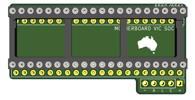
I hope that it will allow me to see what signals the 6560 outputs natively, then start to build on that.
BTW, yes I know there are boards out there that already do this. I've not had much luck with the free or paid-for boards, so I want to ... TRY TO ... understand it myself. Let's see ...
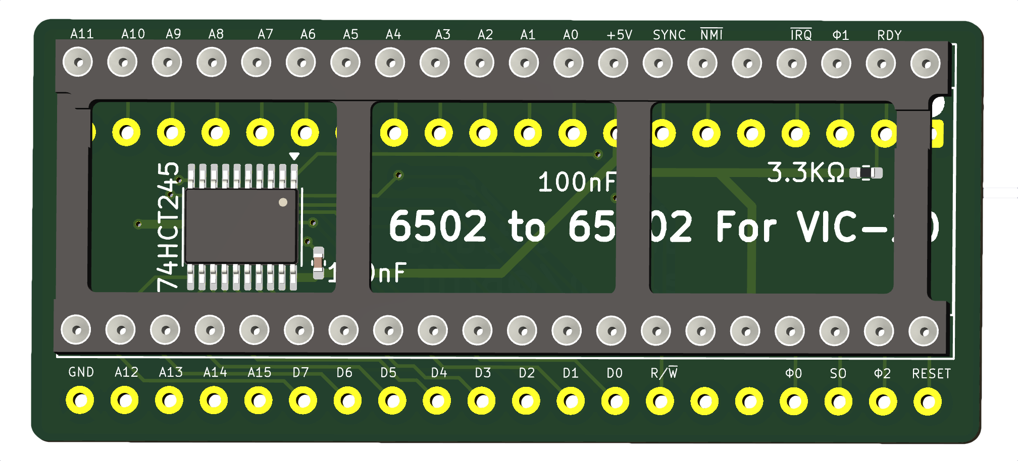
Unlike the 6522 VIAs that can be directly swapped for modern CMOS 65C22s from WDC, the W65C02S can't be directly swapped - a daughterboard is required to buffer the data bus signals and also handle some other signals/pins that differ.
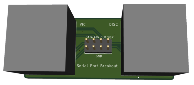
I'm curious how JiffyDOS does its thing so whipped up a simple breakout board for the serial port so I can quickly and very easily connect up my logic analyser to capture the signalling with & without JiffyDOS.
Connect the board to the VIC & the disc drive with a DIN-6, and then a 2x4 Dupont-style cable for the logic analyser.
Okay, my mind is full of ideas so it's probably a bit confusing with all these different designs.
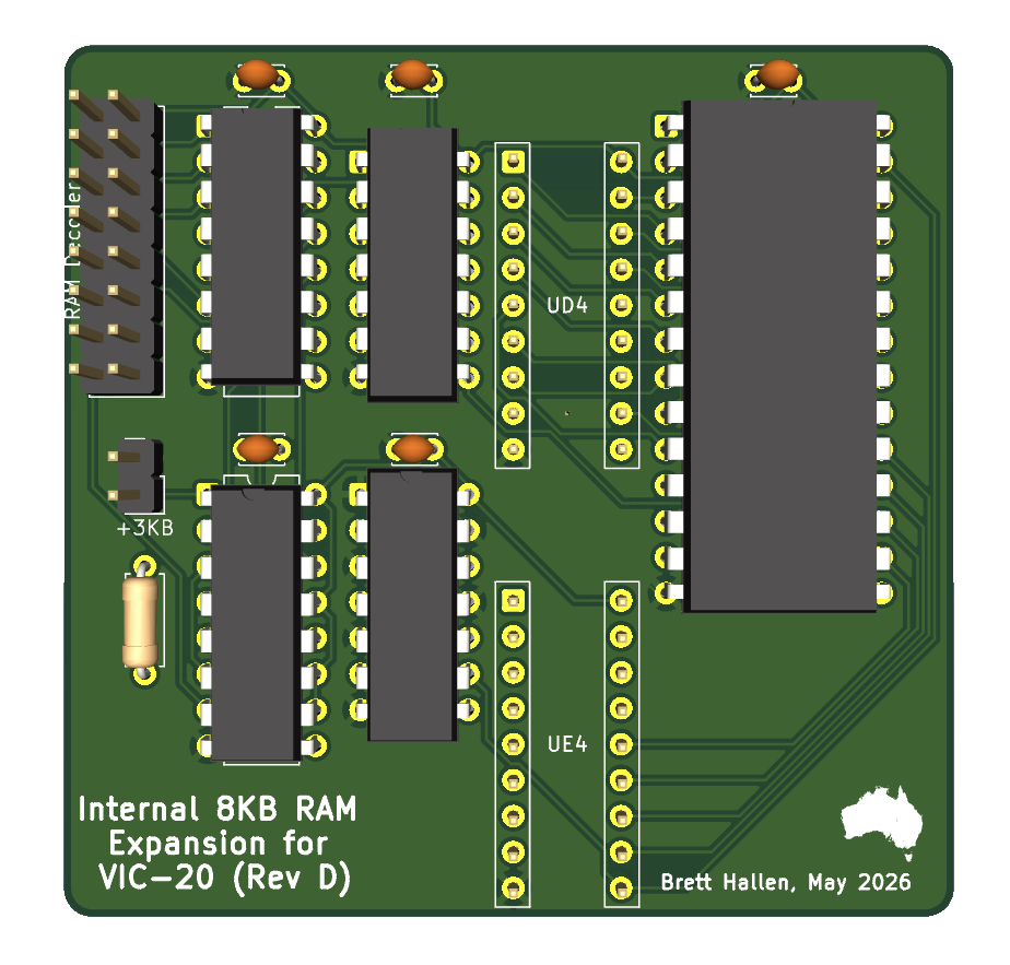
My original intent/idea was to replace the orignal ten 2114 RAM chips in case they were faulty. It then grew from there.
The different designs are:
My attempt to replace the VIC's built in 5KB of RAM (ten 2114 chips) with a single 8KB chip, with an extra 3KB RAM as a free bonus.
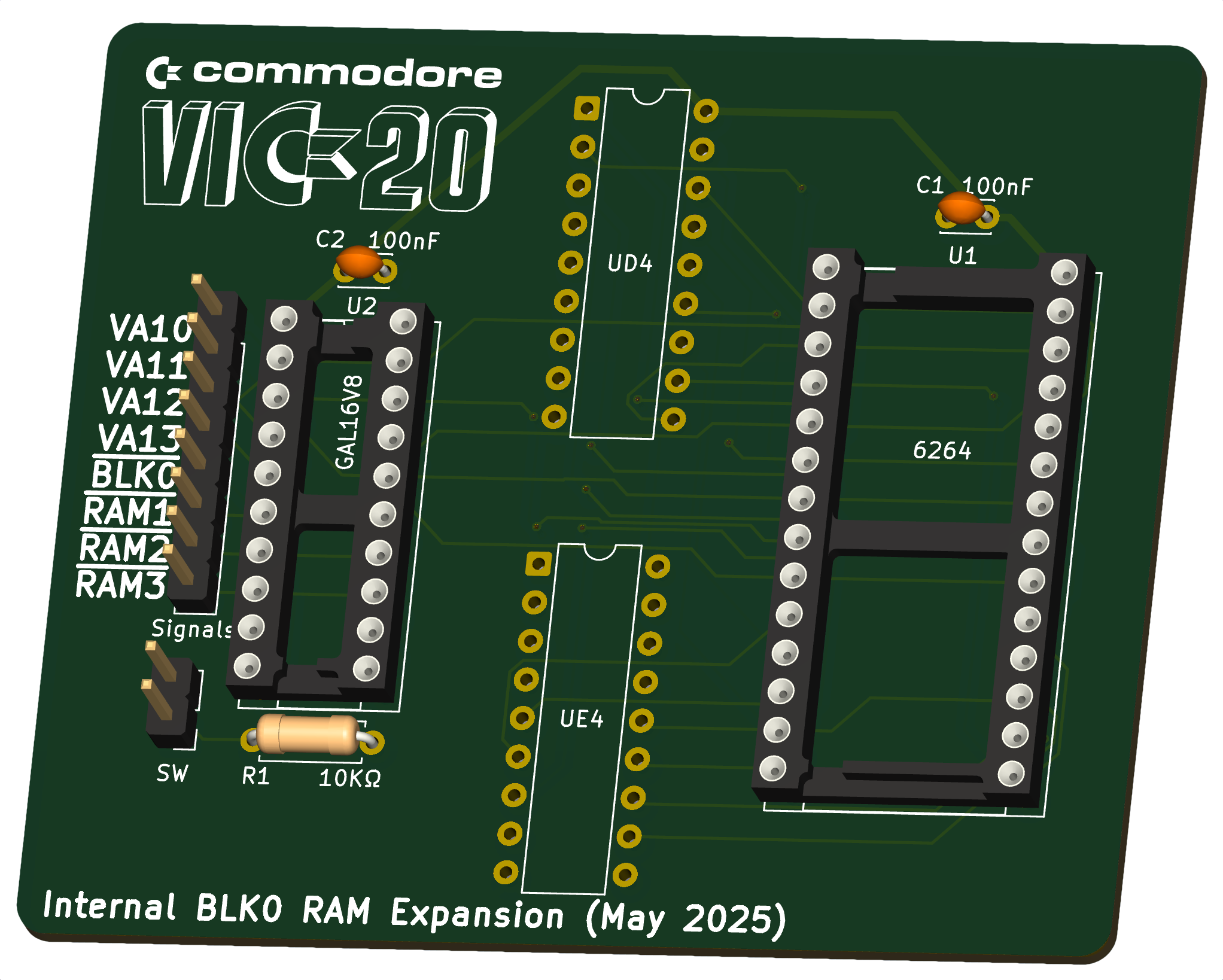
Removes the PLD and re-uses the 74LS138.
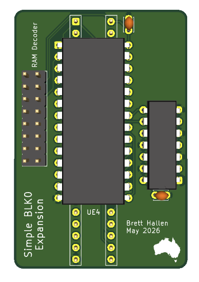
Just the 8KB for BLK0, nothing else. As simple as my simple mind can make it.
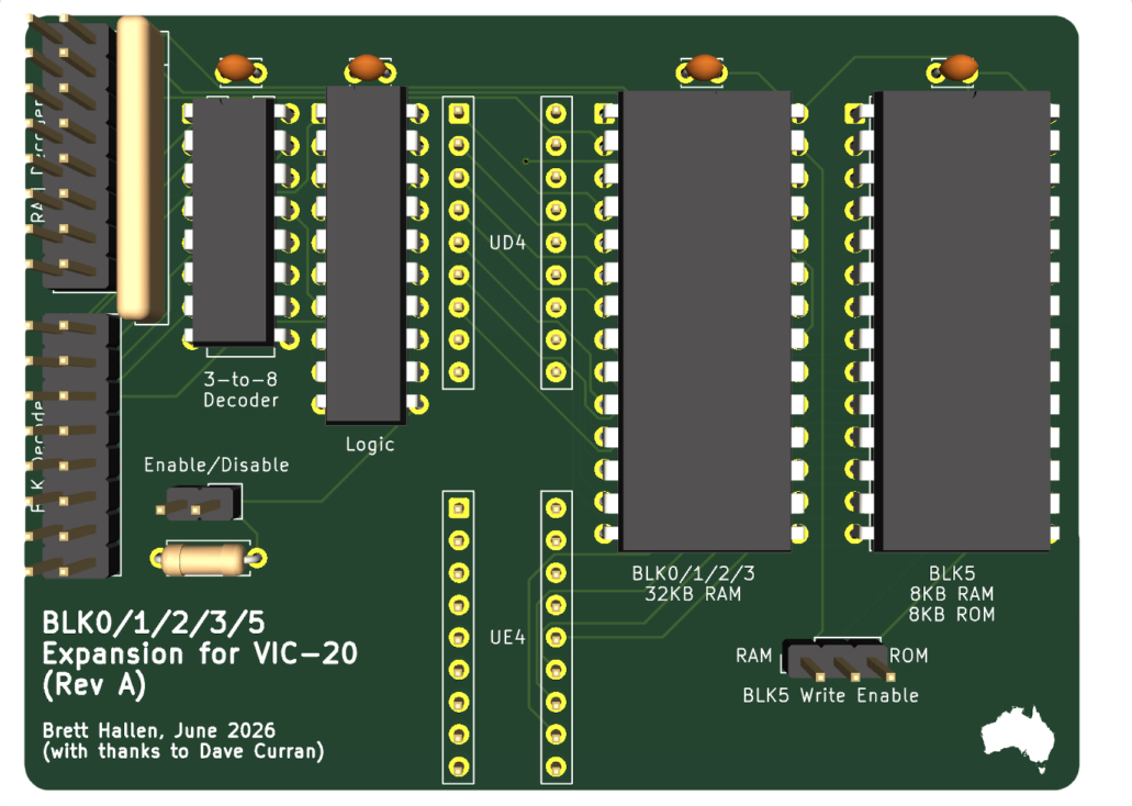
I've obsoleted the 32KB design and gone for this: the full 32KB of RAM in BLK0/1/2/3 plus an addition 8KB RAM or ROM in BLK5.
The BLK1/2/3/5 are switchable off externally for software compatibility, and the BLK5 can be filled with either a 6264 SRAM or 2764/2864 (E)EPROM. There is a header to switch whether it is writable (RAM) or not (ROM).
| Qty | Value | Footprint | References |
|---|---|---|---|
| 2 | SHIFT | Button_Switch_THT:SW_PUSH_6mm | SW12, SW51 |
| 1 | * | Button_Switch_THT:SW_PUSH_6mm | SW15 |
| 1 | + | Button_Switch_THT:SW_PUSH_6mm | SW32 |
| 1 | , < | Button_Switch_THT:SW_PUSH_6mm | SW26 |
| 1 | - | Button_Switch_THT:SW_PUSH_6mm | SW18 |
| 1 | . > | Button_Switch_THT:SW_PUSH_6mm | SW24 |
| 1 | / ? | Button_Switch_THT:SW_PUSH_6mm | SW13 |
| 1 | 0 | Button_Switch_THT:SW_PUSH_6mm | SW17 |
| 1 | 1 ! | Button_Switch_THT:SW_PUSH_6mm | SW61 |
| 1 | 2 " | Button_Switch_THT:SW_PUSH_6mm | SW33 |
| 1 | 3 # | Button_Switch_THT:SW_PUSH_6mm | SW63 |
| 1 | 4 $ | Button_Switch_THT:SW_PUSH_6mm | SW35 |
| 1 | 5 % | Button_Switch_THT:SW_PUSH_6mm | SW62 |
| 1 | 6 & | Button_Switch_THT:SW_PUSH_6mm | SW34 |
| 1 | 7 ' | Button_Switch_THT:SW_PUSH_6mm | SW64 |
| 1 | 8 ( | Button_Switch_THT:SW_PUSH_6mm | SW36 |
| 1 | 9 ) | Button_Switch_THT:SW_PUSH_6mm | SW31 |
| 1 | : [ | Button_Switch_THT:SW_PUSH_6mm | SW22 |
| 1 | ; ] | Button_Switch_THT:SW_PUSH_6mm | SW14 |
| 1 | <- | Button_Switch_THT:SW_PUSH_6mm | SW57 |
| 1 | = | Button_Switch_THT:SW_PUSH_6mm | SW11 |
| 1 | @ | Button_Switch_THT:SW_PUSH_6mm | SW20 |
| 1 | A | Button_Switch_THT:SW_PUSH_6mm | SW55 |
| 1 | B | Button_Switch_THT:SW_PUSH_6mm | SW48 |
| 1 | C | Button_Switch_THT:SW_PUSH_6mm | SW46 |
| 1 | C= | Button_Switch_THT:SW_PUSH_6mm | SW41 |
| 1 | CTRL | Button_Switch_THT:SW_PUSH_6mm | SW53 |
| 1 | D | Button_Switch_THT:SW_PUSH_6mm | SW54 |
| 1 | DEL/INST | Button_Switch_THT:SW_PUSH_6mm | SW8 |
| 1 | DOWN/UP | Button_Switch_THT:SW_PUSH_6mm | SW5 |
| 1 | E | Button_Switch_THT:SW_PUSH_6mm | SW39 |
| 1 | F | Button_Switch_THT:SW_PUSH_6mm | SW42 |
| 1 | F1/F2 | Button_Switch_THT:SW_PUSH_6mm | SW4 |
| 1 | F3/F4 | Button_Switch_THT:SW_PUSH_6mm | SW3 |
| 1 | F5/F6 | Button_Switch_THT:SW_PUSH_6mm | SW2 |
| 1 | F7/F8 | Button_Switch_THT:SW_PUSH_6mm | SW1 |
| 1 | G | Button_Switch_THT:SW_PUSH_6mm | SW56 |
| 1 | H | Button_Switch_THT:SW_PUSH_6mm | SW44 |
| 1 | HOME/CLR | Button_Switch_THT:SW_PUSH_6mm | SW9 |
| 1 | I | Button_Switch_THT:SW_PUSH_6mm | SW29 |
| 1 | J | Button_Switch_THT:SW_PUSH_6mm | SW27 |
| 1 | K | Button_Switch_THT:SW_PUSH_6mm | SW21 |
| 1 | KEYBOARD | Connector_PinHeader_2.54mm:PinHeader_1x20_P2.54mm_Vertical | J1 |
| 1 | L | Button_Switch_THT:SW_PUSH_6mm | SW28 |
| 1 | M | Button_Switch_THT:SW_PUSH_6mm | SW23 |
| 1 | N | Button_Switch_THT:SW_PUSH_6mm | SW25 |
| 1 | O | Button_Switch_THT:SW_PUSH_6mm | SW19 |
| 1 | P | Button_Switch_THT:SW_PUSH_6mm | SW30 |
| 1 | Q | Button_Switch_THT:SW_PUSH_6mm | SW37 |
| 1 | R | Button_Switch_THT:SW_PUSH_6mm | SW58 |
| 1 | RESTORE | Button_Switch_THT:SW_PUSH_6mm | SW65 |
| 1 | RETURN | Button_Switch_THT:SW_PUSH_6mm | SW7 |
| 1 | RIGHT/LEFT | Button_Switch_THT:SW_PUSH_6mm | SW6 |
| 1 | RUN/STOP | Button_Switch_THT:SW_PUSH_6mm | SW49 |
| 1 | S | Button_Switch_THT:SW_PUSH_6mm | SW43 |
| 1 | SPACE | Button_Switch_THT:SW_PUSH_6mm | SW45 |
| 1 | T | Button_Switch_THT:SW_PUSH_6mm | SW38 |
| 1 | U | Button_Switch_THT:SW_PUSH_6mm | SW40 |
| 1 | V | Button_Switch_THT:SW_PUSH_6mm | SW52 |
| 1 | W | Button_Switch_THT:SW_PUSH_6mm | SW59 |
| 1 | X | Button_Switch_THT:SW_PUSH_6mm | SW50 |
| 1 | Y | Button_Switch_THT:SW_PUSH_6mm | SW60 |
| 1 | Z | Button_Switch_THT:SW_PUSH_6mm | SW47 |
| 1 | ^ | Button_Switch_THT:SW_PUSH_6mm | SW10 |
| 1 | £ | Button_Switch_THT:SW_PUSH_6mm | SW16 |


BrettHallen/Commodore_VIC20
Hardware & information for the VIC-20


hackclub/OnBoard
💡 Join 1,000 teenagers and make your first PCB with a $100 grant!


famichu/MagLev_Switch_MX
The 3D printable magnetic levitation contactless switch with the linear output hall effect sensor.

mmccoyd/hillside
Family of split ergonomic keyboards with three rows of six or five keys and a generous thumb arc


Ardumower/ardumower
Develop an open source robotic lawn mower (HW+SW reference platform)
It measures 173 × 55 mm and has 2 copper layers, 1.6 mm thick.
66 parts. The full list of its parts is on this page, with links to each part's symbol and footprint where PCBKit's library has them.
From the BrettHallen/Commodore_VIC20 repository on GitHub, at the commit this page was made from: the board is Keyboard_Tactile_6mm/VIC-20_Tactile_6mm.kicad_pcb and its schematic 6502-to-65C02/KiCad/RevA/6502-to-65C02.kicad_sch. PCBKit opens the board in the browser, with nothing to install.
Its repository states no licence, so its author keeps all rights: ask BrettHallen before reusing the design.