

8 layers118 × 100 mm
Kria k26-devboard
antmicro/kria-k26-devboard
Open source AMD Xilinx Kria UltraScale+ SoM baseboard
660 parts83Apache-2.0

 BniX-exe/LTC4364-Arduino-Shield
KiCad reconstruction of my LTC4364 Arduino Uno shield from reference screenshots; routed PCB, schematic, BOM and validation notes.
LTC4364-Arduino Shield is an open-source printed circuit board by BniX-exe, from the BniX-exe/LTC4364-Arduino-Shield repository on GitHub. It is a 2-layer board of 73 × 103 mm with 24 parts on 50 nets, routed with 214 tracks and 10 vias.
It is built around the ARDUINO UNO R3 and BSS123. Its parts include 7 resistors, 3 diodes, 3 transistors, 3 connectors and 2 capacitors. It belongs with the microcontroller boards boards and the AVR (ATmega, ATtiny) boards of this library.
An editable KiCad reconstruction of a board I drew during my internship, recreated from the schematic and PCB screenshots available in reference/. The original project files were unavailable. This repository documents the reconstructed design; it does not establish that the original or reconstructed board was manufactured or tested.
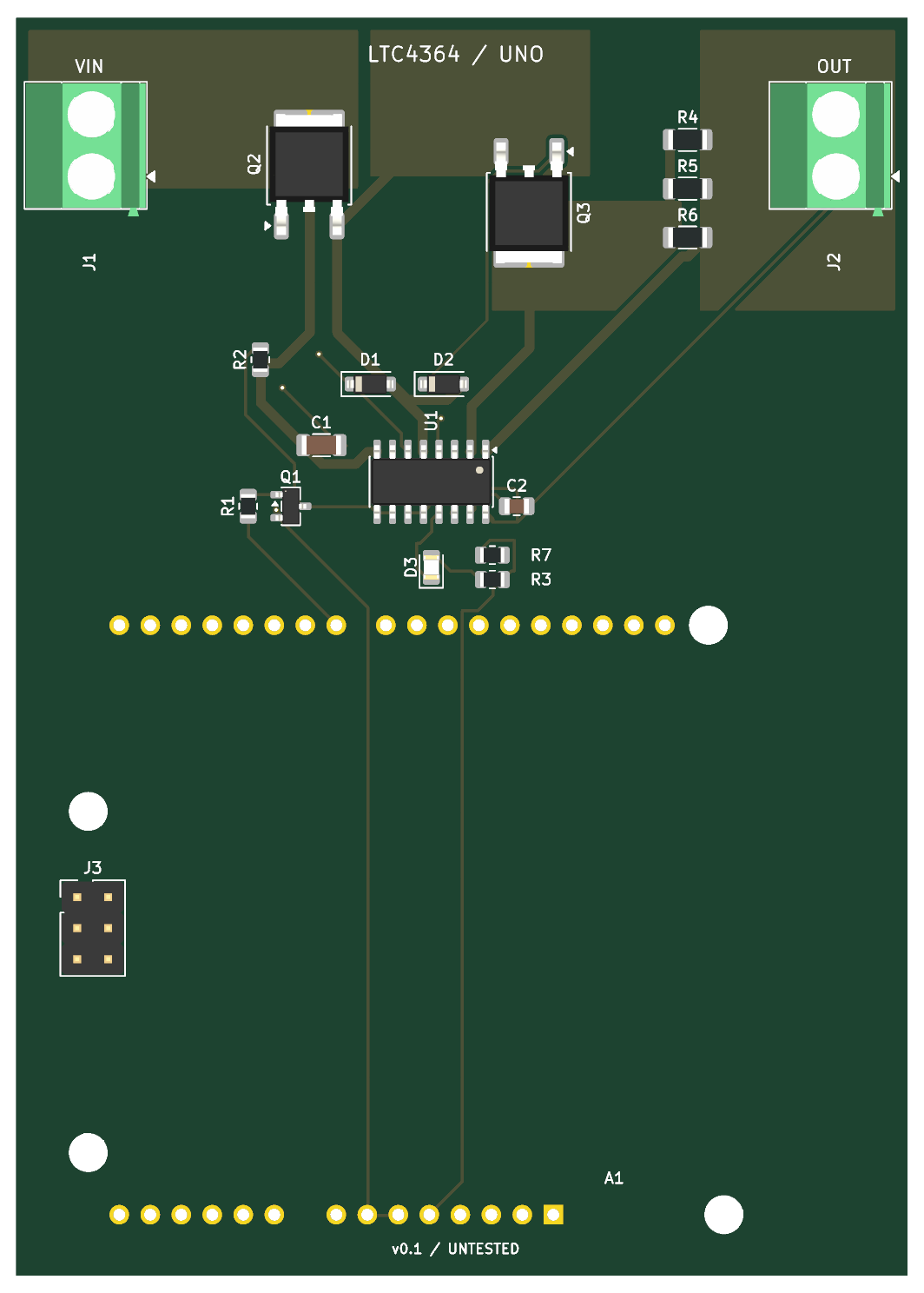
Open LTC4364-Arduino-Shield.kicad_pro in KiCad 10.0 or later. The repository includes the schematic, routed two-layer PCB, BOM, the project-local Arduino header footprint, and inspection outputs. All other footprints and 3D models use the standard KiCad libraries. fp-lib-table points to Reconstruction.pretty through ${KIPRJMOD}.
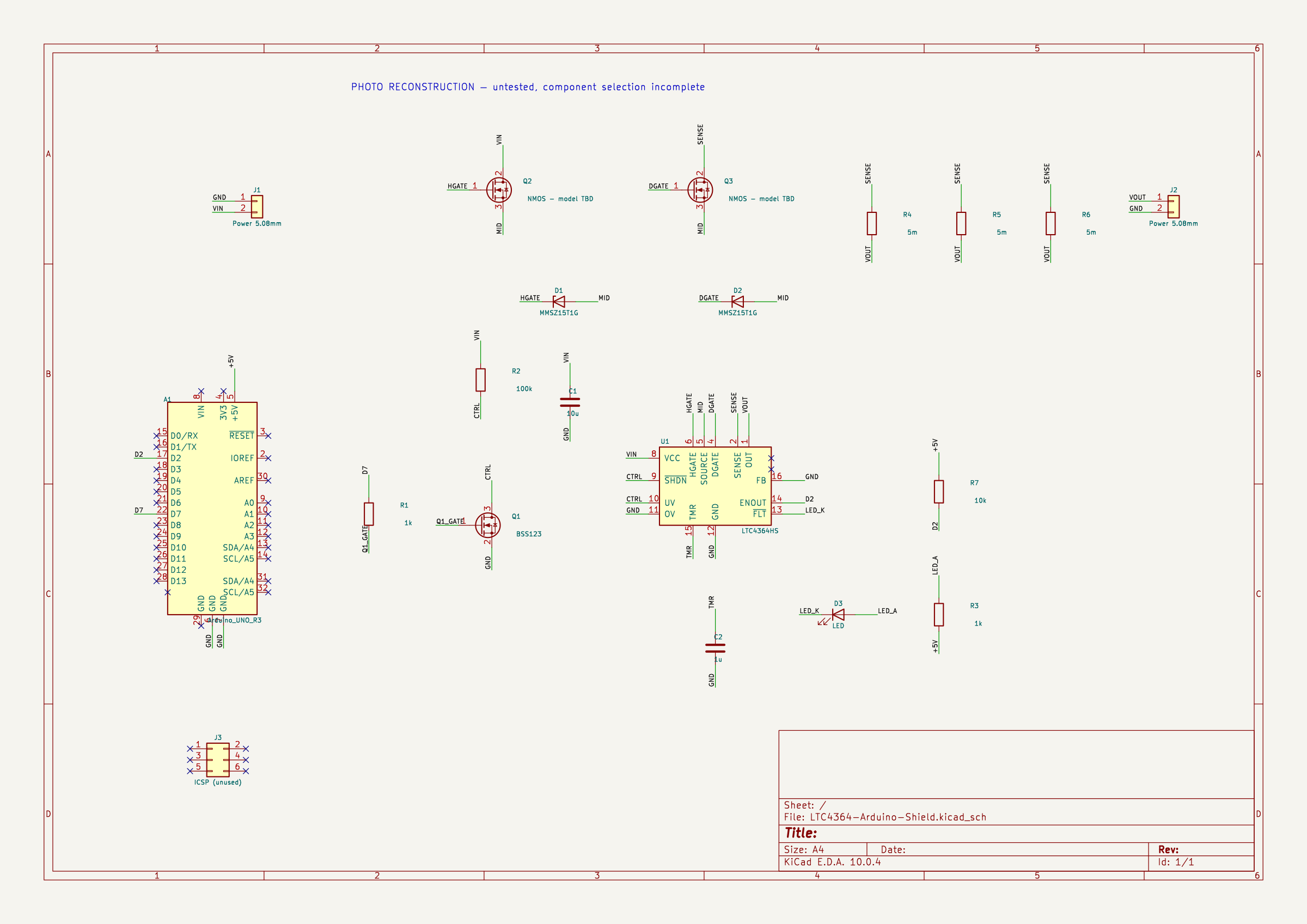
The screenshot's “+60V” label is retained as historical context only. It is not a verified operating rating.
| Item | Status |
|---|---|
| Outline | Inferred 73 × 103 mm rectangle, not a measured copy |
| Arduino headers | Standard Uno R3 2.54 mm geometry; separate unused 2×3 ICSP header |
| Mounting holes | Standard Uno R3 hole coordinates, 3.2 mm drill; screw-head and enclosure fit unverified |
| U1 | Photograph says LTC4364HS; the -1 latch-off / -2 retry suffix is unknown. The stock CS symbol shares the SOIC-16 pinout and the instance value is HS |
| Q2, Q3 | Exact manufacturer/model unknown; BOM deliberately leaves them unselected |
| Power MOSFET pins | Physical footprint uses 1=G, 2=D/tab, 3=S. Generic DGS pin numbering from the screenshot was translated by electrical function |
| Passives | 0805 control passives, 1206 input capacitor and shunts, SOD-123 zeners are inferred from the pictures |
| Routing | Newly routed, with copper zones; not an exact recovery of the photographed copper geometry |
FB and OV are grounded as in the reference, so no feedback-divider surge clamp or OV-input threshold is configured here. SHDN and UV share the pulled-up control node; no useful input undervoltage threshold is established by that connection. Q1 has no added gate pull-down, matching the reference; its reset/start-up behavior needs review.
The three shunts have a nominal combined resistance of about 1.67 mΩ. Applying the datasheet's typical 50 mV current-sense threshold gives about 30 A, not a supported board current rating. MOSFET safe operating area, shunt dissipation/tolerance, terminal ratings, trace and zone capacity, copper thickness, thermal behavior, capacitor voltage rating and transients have not been qualified. Select these parts and review the circuit before powering hardware. This version is a portfolio reconstruction, not a released manufacturing design; Gerbers are intentionally not presented as a qualified production release.
Checked with KiCad 10.0.4 after filling zones:
Reconstruction library is not enabled in its current configuration. The footprint geometry is embedded in the PCB and supplied in the local library; if the editor shows this warning, add/enable Reconstruction.pretty in the project's footprint-library table before updating footprints.The complete report is in docs/drc-report.json. These software checks do not verify electrical function or fabrication suitability. No hardware measurements are claimed.
Analog Devices LTC4364 datasheet. The supplied screenshots are kept separately in reference/ to distinguish visible source information from reconstruction assumptions.
| Qty | Value | Footprint | References |
|---|---|---|---|
| 4 | MountingHole_3.2mm_M3 | MountingHole_3.2mm_M3 | H1, H2, H3, H4 |
| 3 | 5m | Resistor_SMD:R_1206_3216Metric | R4, R5, R6 |
| 2 | 1k | Resistor_SMD:R_0805_2012Metric | R1, R3 |
| 2 | MMSZ15T1G | Diode_SMD:D_SOD-123 | D1, D2 |
| 2 | NMOS - model TBD | Package_TO_SOT_SMD:TO-252-2 | Q2, Q3 |
| 2 | Power 5.08mm | TerminalBlock_Phoenix:TerminalBlock_Phoenix_MKDS-1,5-2-5.08_1x02_P5.08mm_Horizontal | J1, J2 |
| 1 | 100k | Resistor_SMD:R_0805_2012Metric | R2 |
| 1 | 10k | Resistor_SMD:R_0805_2012Metric | R7 |
| 1 | 10u | Capacitor_SMD:C_1206_3216Metric | C1 |
| 1 | 1u | Capacitor_SMD:C_0805_2012Metric | C2 |
| 1 | Arduino_UNO_R3 | Reconstruction:Arduino_UNO_R3_Headers | A1 |
| 1 | BSS123 | Package_TO_SOT_SMD:SOT-23 | Q1 |
| 1 | ICSP (unused) | Connector_PinHeader_2.54mm:PinHeader_2x03_P2.54mm_Vertical | J3 |
| 1 | LED | LED_SMD:LED_0805_2012Metric | D3 |
| 1 | LTC4364HS | Package_SO:SOIC-16_3.9x9.9mm_P1.27mm | U1 |
antmicro/kria-k26-devboard
Open source AMD Xilinx Kria UltraScale+ SoM baseboard

anthony-bernaert/ftdi-jtag-programmer
FTDI-based JTAG Programmer Circuit for FPGAs

RichardRozehnal/Gotek-Floppy-Disk-Emulator-V2
Floppy disk emulator for old computers and machines, Amiga, Atari ST, etc.

antmicro/lpddr4-test-board
Experimental development board interfacing Xilinx Kintex-7 FPGA with LPDDR4 SDRAM

tdjastrzebski/All-Purpose-Power-Micro-Controller
General purpose power controller, capable of driving soldering irons using different voltages and probe types.

antmicro/m2-smart-iot-module
https://antmicro.com/blog/2021/08/open-hardware-smart-m2-radio-module-for-iot/

BelaPlatform/gliss-hardware
You can find the source KiCad files for the Gliss module in this repository. This project is open hardware and under the Creative Commons Share Alike license 4.0.

It measures 73 × 103 mm and has 2 copper layers, 1.6 mm thick.
24 parts, built around the ARDUINO UNO R3 and BSS123. The full list of its parts is on this page, with links to each part's symbol and footprint where PCBKit's library has them.
From the BniX-exe/LTC4364-Arduino-Shield repository on GitHub, at the commit this page was made from: the board is LTC4364-Arduino-Shield.kicad_pcb and its schematic LTC4364-Arduino-Shield.kicad_sch. PCBKit opens the board in the browser, with nothing to install.
Its repository states no licence, so its author keeps all rights: ask BniX-exe before reusing the design.