Skip to the content
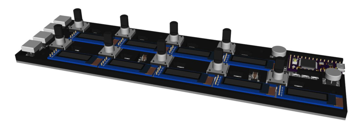
2 layers221 × 61 mmEncoderBoard, the printed circuit board in 3D

A 9-encoder (un-official) add on to the ETC Eos Family of Lighting Consoles and Software, using OSC over USB

Size
221 × 61 mm
Copper layers
2
Thickness
1.6 mm
Parts
228
Nets
158
Pads
862
Tracks, vias
2,178, 134
Pours
1
Routed
Yes
KiCad
KiCad 5 (file 20171130)
Created
2 Jun 2020
Updated
10 Oct 2022

Overview

EncoderBoard is an open-source printed circuit board by BlakeGarner, from the BlakeGarner/encoders-for-etc-eos repository on GitHub, published under the Apache-2.0 licence. It is a 2-layer board of 221 × 61 mm with 228 parts on 158 nets, routed with 2,178 tracks and 134 vias.

It is built around the 74HCT245, 74LVC14AD and WS2812B. Its parts include 95 resistors, 75 capacitors, 26 ICs, 15 switches and 12 diodes. It belongs with the NXP (LPC, Kinetis, i.MX RT) boards of this library.

Main components

3

README

Hardware/README.md

Encoders for ETC Eos Hardware

This folder contains all the design files required to build the Encoders for ETC Eos hardware.

The PCB layout and acrylic case aligment was done using KiCad 5.1. The PCB and case was 3D modelled using FreeCAD v0.18 and the KiCAD StepUp plugin.

This is an independent project that is designed to work with the ETC Eos, but not affiliated with Electronic Theatre Controls in any way.

Installation

Step 1: Order PCB, Parts and Acrylic Case

PCB

The schematic and PCB files were built using KiCad 5.1. But you only need the PCB Gerbers located in the Gerbers folder to order your PCB. I ordered a black PCB so it matched(-ish) the black of my acrylic case.

Electronic Parts

A list of the required components can be found in the BOM folder in either csv or xlsx format.

  • You may need to choose an encoder with a different shaft height than the 20mm I used depending on the internal height of your encoder knobs and space taken up by the acrylic case.
  • Don't forget 0.1" headers to solder the Teensy and OLEDs to the PCB.
  • Be sure to pay special attention to the component package size on the PCB (and listed in the BOM spreadsheet) when choosing your resistors, capacitors and ICs.
  • I sourced most of my components from Digikey or Mouser. You may wish to source the Teensy directly from PJRC (or a distributor) and the WS2812B LEDs and 128x32 OLED displays may be easier and cheaper to source from somewhere like AliExpress. Just be sure the pins are in the same order as the PCB expects!
Acrylic Case

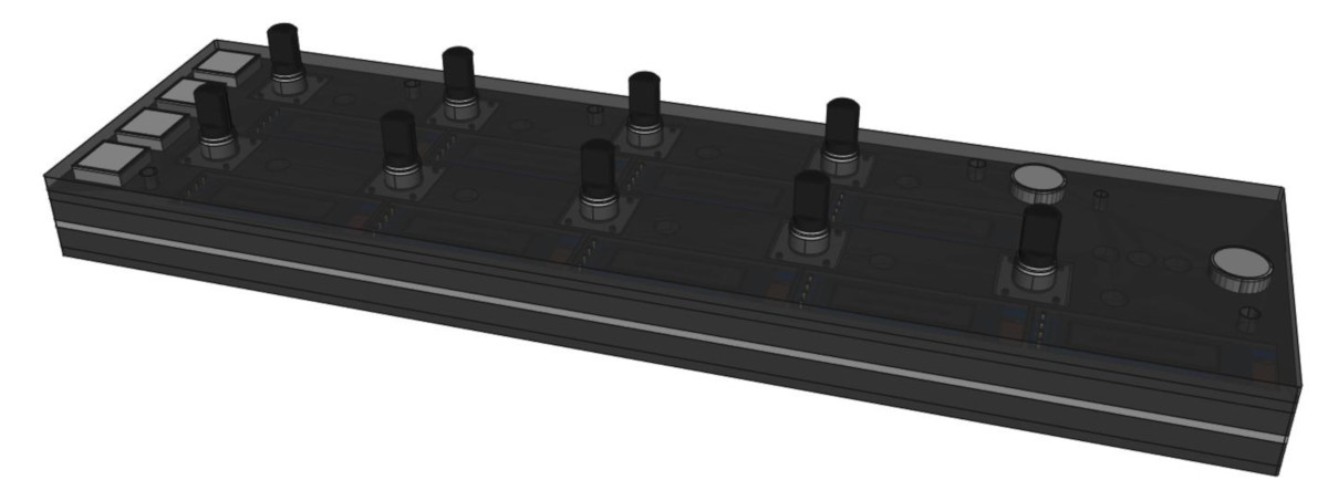
The laser-cut acrylic case is quite an expensive solution compared to off-the-shelf enclosures, but it keeps the encoder case slender and elegant.

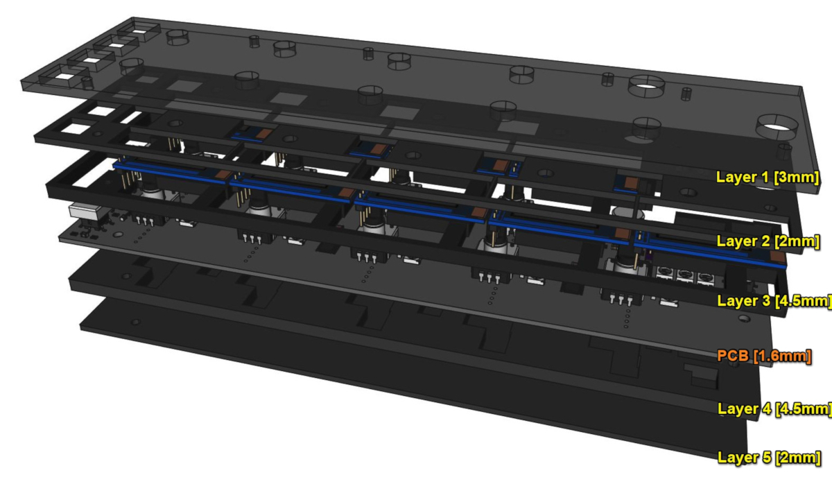
  • The case has five layers:
    Encoder Layers Exploded View
    • Layer 1: The top (clear or semi-transparent) layer - 3mm to bring the total height of the case flush with the push buttons.
    • Layer 2: This is the middle layer of the three above-the-PCB layers. It has cutouts only for the components that need to be visible or poke through the top (transparent) layer: encoders, buttons, LEDs, displays and screw holes.
    • Layer 3: This is essentially a spacer between the PCB and layer 2 so none of the electronic components get in the way. It needs to be thicker than the height of your tallest component - 4.5mm was used in the drawings.
    • Layer 4: This is the spacer for your electronic components on the rear side of the board. 4.5mm acrylic was chosen to match that of layer 3.
    • Layer 5: This is a cover plate for the rear side - 2mm was selected to match that of layer 2.
  • You should be able to order the acrylic from your local laser-cutter supplier. Make sure the requirements in file format and line colours from your laser cutter matches what is supplied. You can find various files in the SVG folder that show the cutouts in a few different layouts.
Extras
  • Some M2.5 screws that are just the right length for all 5 layers + the PCB (1.6mm usually) + nut. I used screws with a 20mm thread and 3mm thick nuts.
  • Some rubber feet that are at least a little deeper than your screw/nut protudes below the case.
  • Knobs for the encoders (check the internal height of the encoder will suit the encoder shaft height).
  • Button caps for the push buttons.

Step 2: Assemble the PCB

  • Solder all parts except the OLED displays to the PCB. I found it easier to do the underside SMT parts first and then the top side SMT parts and finally the PTH parts. The Interactive HTML BOM page in the bom folder should assist when placing components.

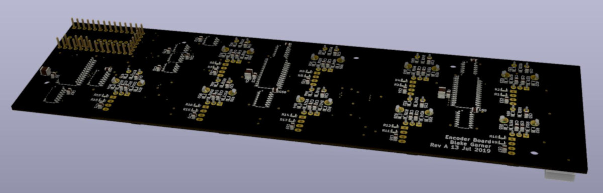
    Encoder PCB Bottom Side

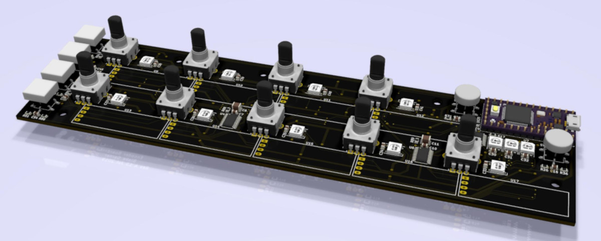
    Encoder PCB Top Side

    • DON'T DO THE OLED DISPLAYS YET! Layer three of the acrylic case needs to go down first.
    • Make sure the Teensy sits within the height of your Layer 3 acrylic (4.5mm).
    • If you've not done SMT soldering before, you may want to practice on a smaller project before attempting this one. SMT soldering is not as hard as it looks but some practice before-hand is advised!
    • Be extra careful with the alignment of the encoders and push buttons when soldering them in place. If they don't line them up perfectly they will likely scrape against the side of the case and not operate correctly.
  • Double check all your soldering work - checking for shorts, missing joints or ICs/diodes in the wrong orientation. Even though the OLEDs are not fitted, it is okay to power on the system to check everything else at this point. I used one spare OLED with pogo-pins fitted that I could then use to check each OLED output one-by-one.

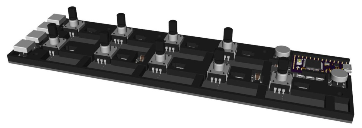
  • Place Layer 3 of the acrylic case on top of the PCB. Check the sections that will sit under the OLEDs will not force the OLEDs to sit proud of layer 2 - I had to sand those spacers down about one millimeter to reduce the height on the OLEDs. Temporarily hold layer 3 and the PCB together using a few screws.
    Encoders with layer 3 acrylic fitted

  • Solder the OLEDs in place, ensuring they will not sit any taller than layer 2 of the acrylic pieces when fitted. Also note that from now on, layer 3 will be fixed in place, and it will no longer be possible to service or re-solder most of the top-mounted SMT components.
    Encoders with OLEDs fitted

Step 3: Fit off the case

  • Remove any temporary screws holding layer 3 in place, then stack the remaining acrylic layers together and screw the five pieces of acrylic + PCB together. Be gentle when tightening the nuts as the acrylic will crack if placed under stress.
    Encoders with all acrylic layers
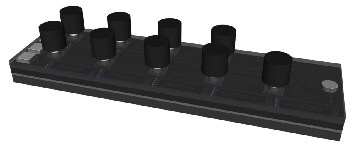
  • Snap the knobs and button caps in place.
    Encoders complete

Step 4: Upload Firmware

  • You need TyCommander or Teensyduino to upload the firmware to the Teensy. TyCommander is a simpler install, but Teensyduino is fine if you already have that installed.
Using TyTools
  • Download TyTools and extract it somewhere convenient.
  • Start up TyCommander.exe
  • Plug in the Teensy on the encoder board.
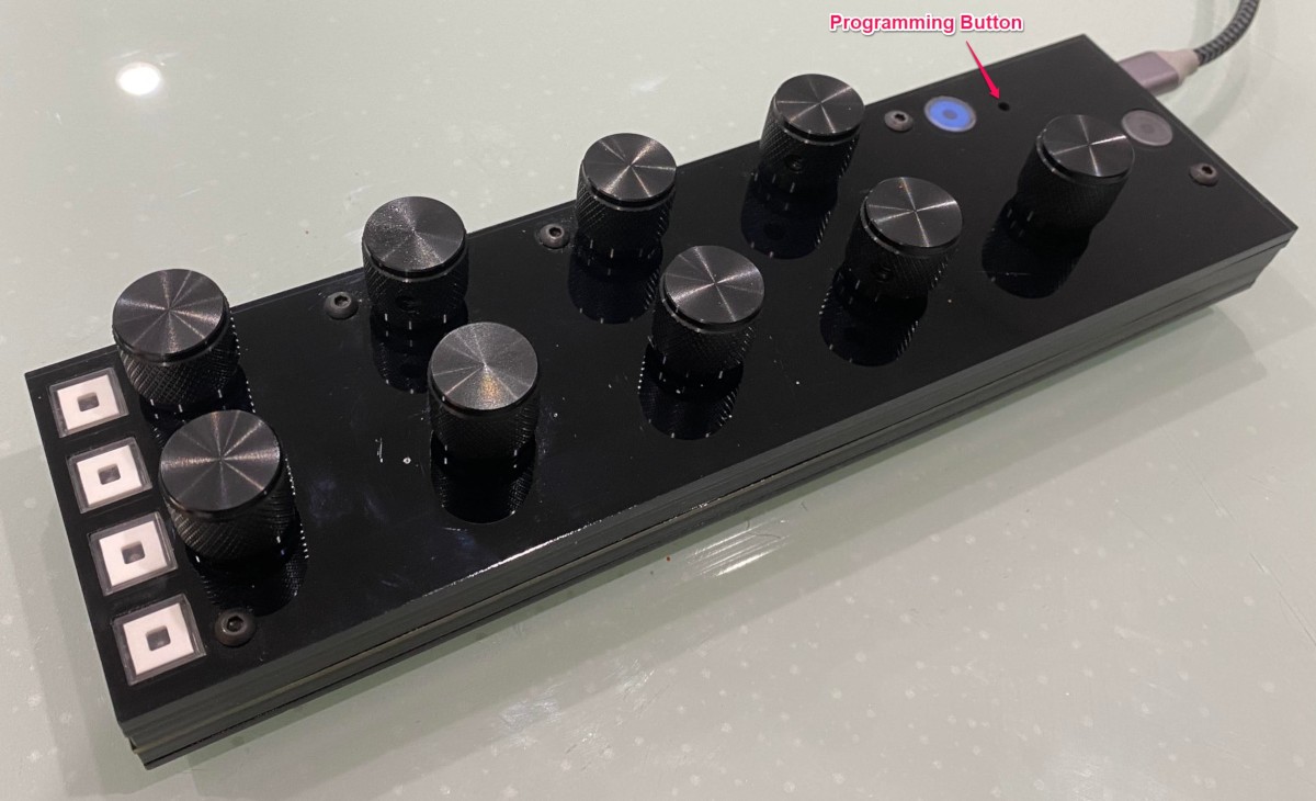
  • Place the Teensy board in programming mode by pressing the push-button on top of the Teensy (still accessible using a paperclip with the case in place). Encoders Programming Button
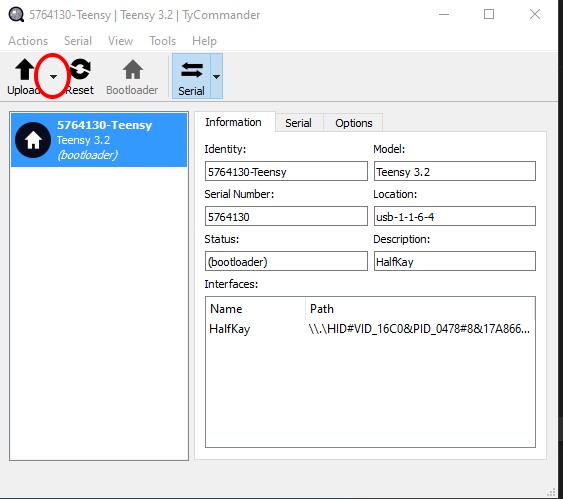
  • The Teensy should show as in bootloader mode and the upload button should become available. Click the drop-down menu on the upload button and choose "Upload New Firmware".
    TyCommander Upload Button
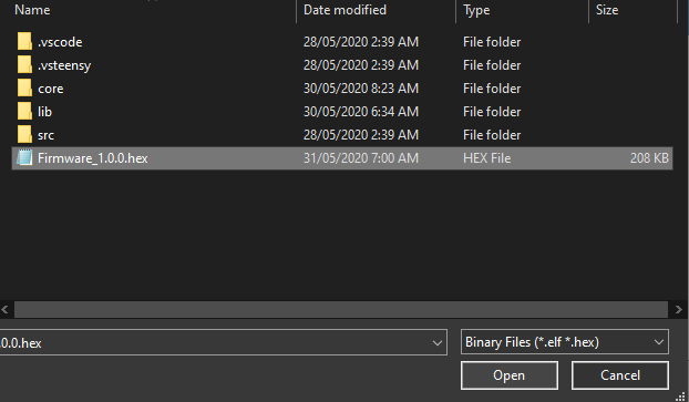
  • Navigate to this project folder and select the Firmware_x.x.x.hex file in the Firmware folder that matches the version you want to upload (probably the latest version).
    TyCommander HEX File Select
  • The firmware will take a couple of seconds to upload, and then the board should automatically reboot.
Using Teensyduino
  • Download the latest Arduino software from the Arduino website, and install it.
  • Download the latest Teensyduino software from the PJRC website, and install it.
  • Open the Teensy.exe file from the Teensyduino installation directory, or via the Arduino software.
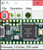
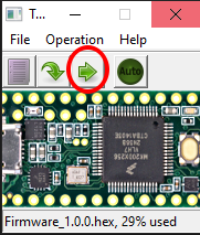
  • Click the "Open HEX File" button.
    Encoders Load HEX File
  • Navigate to this project folder and select the Firmware_x.x.x.hex file in the Firmware folder that matches the version you want to upload (probably the latest version).
  • Place the Teensy board in programming mode by pressing the push-button on top of the Teensy (still accessible using a paperclip with the case in place).
    Encoders Programming Button
  • Program the Teensy by pressing the Program button in the Teensy utility.
    Teensy Program Button
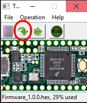
  • Reset the Teensy by pressing the Reset button in the Teensy utility. The board should then reboot and start up as normal.
    Teensy Reset Button
  • Note: If the Auto button is enabled on the Teensy app, it will do the program + reset as soon Teensy is placed into programming mode.

Step 5: Test

The encoder board should now be working. Connect it to an Eos family console, or ETCnomad software as described on the home page and give it a spin!

Issues

  • In revA of the board, there are some missing pull-up resistors for the push buttons that need to be bodged onto the PCB - fixed in RevB of the board.
  • Some of the acrylic can be a tight fit, depending on your laser-cutter's tolerances. Best to approach the fitting of the board on a day when you have plenty of paitence! I will try to make it more forgiving in later revisions.
  • See the Todo text file for a list of issues found when building the most recent revision of the board, as well as desired improvements for future versions.

Contributing

Contributions are most welcome! Please log an issue and/or pull request for any bugs or feature changes you may wish to share.

Credits

ETC LightHack which formed the basis and initial inspiration for this project

License

All hardware files (inside EncoderBoard) uses the Apache 2.0 license. See LICENSE for more information.

Parts

228
QtyValueFootprintReferences
6610kResistor_BG:R_0805_2012MetricR22, R23, R24, R25, R27, R28, R29, R30, R32, R33, R34, R35, R36, R37, R39, R40 +50
52100nFCapacitor_BG:C_0805_2012MetricC1, C3, C10, C14, C15, C18, C19, C20, C25, C26, C27, C28, C30, C31, C32, C33 +36
224.7kResistor_BG:R_0805_2012MetricR1, R2, R3, R4, R5, R10, R11, R12, R13, R14, R15, R16, R18, R19, R20, R21 +6
1810nFCapacitor_BG:C_0805_2012MetricC12, C13, C16, C17, C21, C22, C23, C24, C29, C42, C43, C44, C48, C49, C50, C51 +2
12WS2812BLED_BG:LED_WS2812B_PLCC4_5.0x5.0mm_P3.2mmD1, D2, D3, D4, D5, D6, D7, D8, D9, D10, D11, D12
9Display_OLED_128x32_I2CDisplay_BG:Display_OLED_128x32_I2CU9, U10, U11, U12, U13, U14, U15, U16, U17
9Rotary_Encoder_SwitchEncoder_BG:RotaryEncoder_Bourns_PEC12R-4x20k-Sxxxx-Switch_Vertical_H20mmSW1, SW2, SW3, SW4, SW5, SW6, SW7, SW8, SW9
674LVC14SOIC_BG:SOIC-14_3.9x8.7mm_P1.27mmU18, U19, U20, U21, U22, U23
510uFCapacitor_BG:C_1210_3225MetricC2, C4, C6, C8, C11
4CAT24M01WSOIC_BG:SOIC-8_3.9x4.9mm_P1.27mmU8, U24, U25, U26
3MCP23S17_SOSOIC_BG:SOIC-28W_7.5x17.9mm_P1.27mmU1, U2, U3
2120Resistor_BG:R_0805_2012MetricR41, R48
2150Resistor_BG:R_0805_2012MetricR26, R38
233Resistor_BG:R_0805_2012MetricR31, R51
2TCA9548APWRTSSOP_BG:TSSOP-24_4.4x7.8mm_P0.65mmU4, U6
1330RResistor_BG:R_0805_2012MetricR17
174HCT245TSSOP_BG:TSSOP-20_4.4x6.5mm_P0.65mmU5
1SW_Push_LED_BlueButton_Switch_BG:E-Switch_SPST_LED_SquareCap_TL3240F160xSW15
1SW_Push_LED_BlueButton_Switch_BG:E-Switch_SPST_LED_RoundCap_TL3240F160xSW11
1SW_Push_LED_GreenButton_Switch_BG:E-Switch_SPST_LED_SquareCap_TL3240F160xSW14
1SW_Push_LED_RedButton_Switch_BG:E-Switch_SPST_Red_LED_SquareCap_TL3240F160RSW12
1SW_Push_LED_RedButton_Switch_BG:E-Switch_SPST_Red_LED_RoundCap_TL3240F160RSW10
1SW_Push_LED_YellowButton_Switch_BG:E-Switch_SPST_LED_SquareCap_TL3240F160xSW13
1Teensy3.2Teensy_BG:Teensy30_31_32_LCU7

The 223 most common of 228 parts.

Similar boards

  • 2 layers114.3 × 188 mmCkt defect array, the printed circuit board in 3D

    Ckt defect array

    IowaScaledEngineering/ckt-defect

    Talking Defect Detector

    338 parts
  • 2 layers100 × 50 mmMini led clock, the printed circuit board in 3D

    Mini led clock

    mmiscool/bobc_hardware

    Various hardware projects

    72 parts
  • 4 layers49 × 30 mmGcvideo lite, the printed circuit board in 3D

    Gcvideo lite

    ikorb/gcvideo

    GameCube Digital AV converter

    44 parts766
  • 4 layers223.3 × 120.1 mmISA FPGA v2, the printed circuit board in 3D

    ISA FPGA v2

    robfinch/Cores

    Cores ===== RTF's Cores Use at your own risk. Welcome to my galaxy of cores. Contained in the directories are IP cores, source code for digital circuits.

    132 parts78
  • 2 layers100 × 80 mmScuznet, the printed circuit board in 3D

    Scuznet

    saybur/scuznet

    Open source hardware emulating a SCSI to Ethernet adapter.

    103 parts39GPL-3.0
  • 4 layers122.2 × 115.1 mmScan controller kicad, the printed circuit board in 3D

    Scan controller kicad

    fwachsmuth/Filmkorn-Raw-Scanner

    The Filmkorn Raw Scanner, turning 8mm and 16mm films into lossless 12-bit CinemaDNG

    170 parts13MIT
  • 4 layers160 × 100.2 mmCsa ultracpu, the printed circuit board in 3D

    Csa ultracpu

    fachat/csa_ultracpu

    The CPU board for a 17MHz Colour-PET clone with modern interfaces

    175 parts9GPL-3.0
  • 4 layers170 × 170 mmITX PiStorm, the printed circuit board in 3D

    ITX PiStorm

    PiStorm/pistorm-mini-itx

    18 parts8

Questions

How big is the EncoderBoard PCB?

It measures 221 × 61 mm and has 2 copper layers, 1.6 mm thick.

What parts does the EncoderBoard use?

228 parts, built around the 74HCT245, 74LVC14AD and WS2812B. The full list of its parts is on this page, with links to each part's symbol and footprint where PCBKit's library has them.

Where can I download the EncoderBoard KiCad files?

From the BlakeGarner/encoders-for-etc-eos repository on GitHub, at the commit this page was made from: the board is Hardware/EncoderBoard.kicad_pcb. PCBKit opens the board in the browser, with nothing to install.

Can I use the EncoderBoard design in my own project?

Its repository publishes it under the Apache-2.0 licence: you may reuse it on that licence's terms (keep the author's notice, and for a copyleft licence share your changes alike).