4 layers87 × 106 mm

 BigSmartt01/Multi-parameter-Medical-Measurement-PCB
PCB design (one layer) for UNILORIN BME STUDENT - 2026 - on a multi parameter medical measurement that records ECG, pulse, temperature, blood pressure
Multi paramter Medicals is an open-source printed circuit board by BigSmartt01, from the BigSmartt01/Multi-parameter-Medical-Measurement-PCB repository on GitHub. It is a 2-layer board of 90.3 × 96.7 mm with 48 parts on 46 nets, routed with 265 tracks and 0 vias.
It is built around the MPXHZ6400AC6T1, DS18B20 and MAX30102, with the IRLB8721PBF and BC337 among its other parts. Its parts include 12 connectors, 11 resistors, 5 diodes, 4 capacitors and 3 transistors. It belongs with the sensors and measurement boards and the ESP32 boards of this library.


Project Topic: Design and Development of a Multi-Parameter Patient Monitoring System with ECG Arrhythmia Detection, Real-Time Data Storage, and Wireless Remote Display.
This repository holds the hardware design (schematic, PCB, footprints, fabrication files) for the patient-side sensor and actuator unit. Firmware and the ML/logic layer on the Raspberry Pi are maintained separately by the software team; this repo covers circuitry only.
The board sits at the patient's bedside and handles all direct sensor and actuator interfacing:
The Raspberry Pi 5 sits on the nurse side, runs the ML model (arrhythmia detection), logic, data storage, and drives an HDMI display plus a web app. It never touches the patient directly, all sensor/actuator interfacing is the ESP32's job.
\[Patient side]                              \[Nurse side]
ESP32 (sensors + actuators + OLED + buzzer)  <--MQTT/WiFi-->  Raspberry Pi 5 (ML, logic, storage, HDMI, web app)
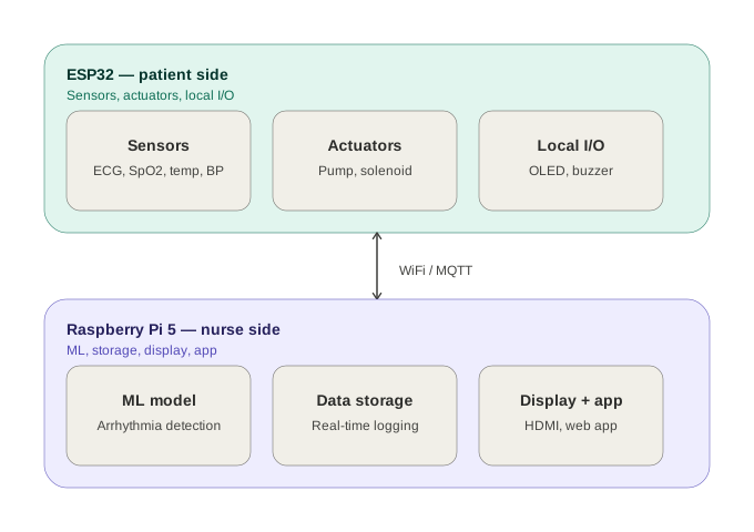
MQTT topic structure (for reference, implemented in firmware):
Pi publishes (commands to ESP32):
pi/control/pumppi/control/valvepi/display/oledpi/control/buzzerPi subscribes (data from ESP32):
esp32/sensors/ecgesp32/sensors/bpesp32/sensors/tempesp32/sensors/pulseesp32/status/pumpA full block diagram will be added to docs/ covering both the electrical and system-level data flow.
Multi-parameter Medical Measurement/
|-- libraries/
|     |-- 3d          (3D models for footprints, if used)
|     |-- footprints   (custom KiCad footprints, e.g. module outlines)
|     |-- symbols      (custom KiCad symbols for breakout modules)
|-- fabrication         (gerbers, drill files, BOM, pick-and-place, for JLCPCB)
|-- kicad                (project file, schematic, PCB layout)
|-- docs (this documentation, block diagrams, reference notes)| Subsystem | Part | Notes |
|---|---|---|
| MCU | ESP32 DevKit V1 (30 GPIO) | Mounted on female header for clearance |
| ECG | AD8232 breakout | LO+/LO- leads-off detection wired in |
| SpO2 / Pulse | MAX30102 breakout | I2C |
| Temperature | DS18B20 | 1-Wire, 4.7k pull-up |
| Blood pressure | MPXHZ6400AC6T1 | SOIC-8, resistor divider scales output for ESP32 ADC |
| Display | 2.4" OLED, SPI, 7-pin | CS tied to GND (only SPI device on board) |
| Alert | Piezo buzzer | Driven through BC337 NPN transistor stage |
| Pump | 12V, MOSFET-switched | IRLB8721, flyback diode, gate pull-down |
| Solenoid/Valve | 12V, MOSFET-switched | IRLB8721, flyback diode, gate pull-down |
| Power | 3x 18650 (3S) + BMS | 12.6V nominal, LM2596 module steps down to 5V |
Full pin mapping and design rationale are in docs/circuit\_documentation.md.
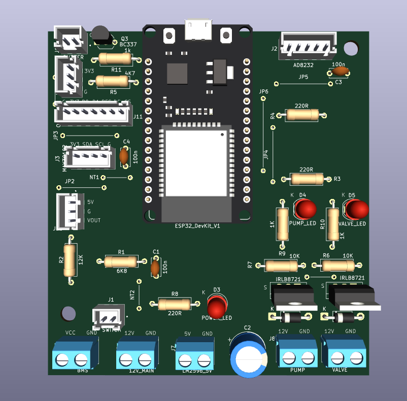
Fabricated single-layer patient-side monitoring board
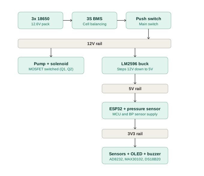
3x 18650 (3S) + BMS -> LM2596 buck -> 5V rail
kicad/Multi-parameter Medicals.kicad\_pro in KiCad 9.0.7 or later.libraries/, make sure these are added to your project's library table before opening the schematic, or KiCad will show missing symbol/footprint errors.Circuit design (schematic + PCB): Smart Ayodele Firmware and ML/logic: student team
| Qty | Value | Footprint | References |
|---|---|---|---|
| 4 | GND_NetTIE | PCM_Jumper_AKL:Jumper_P7.62mm_D0.7mm | NT1, NT2, NT3, NT4 |
| 3 | 100n | Capacitor_THT:C_Disc_D5.0mm_W2.5mm_P5.00mm | C1, C3, C4 |
| 3 | 220R | Resistor_THT:R_Axial_DIN0309_L9.0mm_D3.2mm_P12.70mm_Horizontal | R3, R4, R8 |
| 2 | 10K | Resistor_THT:R_Axial_DIN0309_L9.0mm_D3.2mm_P12.70mm_Horizontal | R6, R7 |
| 2 | 1K | Resistor_THT:R_Axial_DIN0309_L9.0mm_D3.2mm_P12.70mm_Horizontal | R9, R10 |
| 2 | 1N4007 | Diode_THT:D_DO-41_SOD81_P10.16mm_Horizontal | D1, D2 |
| 2 | 3V3_JUMPER | PCM_Jumper_AKL:Jumper_P15.24mm_D0.7mm | JP3, JP5 |
| 2 | IRLB8721 | Package_TO_SOT_THT:TO-220-3_Vertical | Q1, Q2 |
| 1 | 1000u | Capacitor_THT:CP_Radial_D10.0mm_P7.50mm | C2 |
| 1 | 12K | Resistor_THT:R_Axial_DIN0309_L9.0mm_D3.2mm_P12.70mm_Horizontal | R2 |
| 1 | 12V_MAIN | footprint_:TB002-500-02BE | J6 |
| 1 | 1k | Resistor_THT:R_Axial_DIN0309_L9.0mm_D3.2mm_P12.70mm_Horizontal | R11 |
| 1 | 4K7 | Resistor_THT:R_Axial_DIN0309_L9.0mm_D3.2mm_P12.70mm_Horizontal | R5 |
| 1 | 5V_JUMPER | PCM_Jumper_AKL:Jumper_P20.32mm_D0.7mm | JP6 |
| 1 | 6K8 | Resistor_THT:R_Axial_DIN0309_L9.0mm_D3.2mm_P12.70mm_Horizontal | R1 |
| 1 | AD8232 | footprint_:JST_B5B-XH-A | J2 |
| 1 | BC337 | Package_TO_SOT_THT:TO-92_Inline_Wide | Q3 |
| 1 | BMS | footprint_:TB002-500-02BE | J5 |
| 1 | BP_JST | footprint_:JST_B3B-XH-A | J12 |
| 1 | BUZZER | footprint_:JST_B2B-XH-A | J10 |
| 1 | DS18B20 | footprint_:JST_B3B-XH-A | J4 |
| 1 | ESP32_DevKit_V1 | PCM_SL_Development_Boards:DOIT_ESP32_DEVKIT_30Pins | A1 |
| 1 | GND_JUMPER | PCM_Jumper_AKL:Jumper_P12.70mm_D0.7mm | JP2 |
| 1 | LM2596_5V | footprint_:TB002-500-02BE | J7 |
| 1 | MAX30102 | footprint_:JST_B4B-XH-A | J3 |
| 1 | MPXHZ6400AC6T1 | footprint_:MPXHZ6400AC6T1 | IC1 |
| 1 | OLED | footprint_:JST_B7B-XH-A | J11 |
| 1 | POWER_LED | LED_THT:LED_D5.0mm | D3 |
| 1 | PUMP | footprint_:TB002-500-02BE | J8 |
| 1 | PUMP_JUMPER | PCM_Jumper_AKL:Jumper_P15.24mm_D0.7mm | JP4 |
| 1 | PUMP_LED | LED_THT:LED_D5.0mm | D4 |
| 1 | SWITCH | footprint_:JST_B2B-XH-A | J1 |
| 1 | VALVE | footprint_:TB002-500-02BE | J9 |
| 1 | VALVE_LED | LED_THT:LED_D5.0mm | D5 |
The 46 most common of 48 parts.

D0kRay/hpe-mini
Clean Hellen One starter structure for a custom rusEFI-compatible PCB.

jgOhYeah/Farm-PJON-LoRa-network
Code relating to a small LoRa network for remote monitoring and control

DaFrancoGui/TCC
Repositório para compilação de arquivos de código e de texto referentes ao meu trabalho de conclusão de curso

SahidZuhdiKaruniawanKelana/Monitoring-Health-System
CliniScan adalah alat pemantau kesehatan berbasis mikrokontroler yang dirancang untuk memonitor detak jantung dan suhu tubuh secara real-time.


pablozg/freeds
Derivador de energía solar excedente creado por Pablo Zerón, Diseño PCB por Amcalo, Tester original por Aeizoon, Wiki por Zoilo Mora

It measures 90.3 × 96.7 mm and has 2 copper layers, 1.6 mm thick.
48 parts, built around the MPXHZ6400AC6T1, DS18B20, MAX30102 and IRLB8721PBF. The full list of its parts is on this page, with links to each part's symbol and footprint where PCBKit's library has them.
From the BigSmartt01/Multi-parameter-Medical-Measurement-PCB repository on GitHub, at the commit this page was made from: the board is kicad/Multi-paramter Medicals.kicad_pcb and its schematic kicad/Multi-paramter Medicals.kicad_sch. PCBKit opens the board in the browser, with nothing to install.
Its repository states no licence, so its author keeps all rights: ask BigSmartt01 before reusing the design.