
2 layers67.3 × 74.9 mm
 BigSmartt01/IoT_O2_Concentrator
An integrated PSU Prototype for Unilorin BME Final year student - set 2026
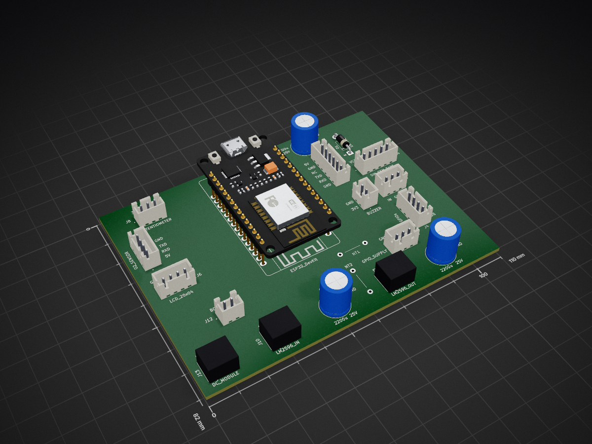
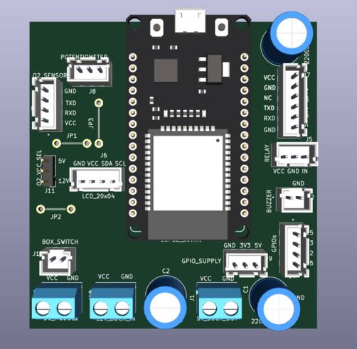
IoT O2 Concentrator is an open-source printed circuit board by BigSmartt01, from the BigSmartt01/IoT_O2_Concentrator repository on GitHub. It is a 2-layer board of 110 × 82 mm with 20 parts on 34 nets, routed with 140 tracks and 0 vias.
It is built around the ESP32-DEVKITM-1. Its parts include 13 connectors, 3 capacitors and 1 diode. It belongs with the home automation and IoT boards and the ESP32 boards of this library.
Purity Monitoring, Alert System and Compressor Control
A non-invasive integration module for PSA oxygen concentrators. The system monitors oxygen purity on the outlet line, escalates alerts through five tiers as purity drops, notifies a caregiver via SMS or voice call, and cuts compressor power only at true system failure levels.
| Feature | Description |
|---|---|
| Purity monitoring | OCS-3FL2.0 ultrasonic sensor on post-filtration outlet (UART2) |
| Local display | LCD 2004 (I2C) shows O2%, flow, temperature, status, GSM signal, uptime |
| Five-tier alerts | NORMAL → WARNING → DANGER → SEVERE → CRITICAL, each with distinct buzzer pattern and response |
| Caregiver config | Number stored in NVS flash — configurable via USB serial, SMS command, or the web portal |
| Three input modes | Potentiometer (demo), WiFi captive portal (demo sliders), or real Sensor (UART) |
| Boot illusion | On boot, simulates a sensor warm-up ramp until a real sensor is connected — no hardware required to demo |
| Fail-safe relay | Compressor only cuts at CRITICAL (near-ambient O2, sustained) — every other tier keeps it running while alerting |
The concentrator itself is not modified. All integration is external in a separate enclosure.
| Component | Role |
|---|---|
| ESP32 DevKit (standard) | Main microcontroller, 3 UARTs, WiFi AP for captive portal |
| OCS-3FL2.0 sensor | Oxygen purity, flow, temperature (UART2, 12-byte packet) |
| SIM800L GSM EVB | SMS and voice call via Nigerian GSM network (UART1) |
| LCD 2004 + I2C backpack | Local display, 4 rows |
| 5V relay module + NPN driver (BC337) | Compressor power control, active-HIGH from GPIO |
| Active buzzer (5V) | Audible alert, pattern varies by tier |
| LM2596 buck converter | 12V to 5V regulated rail |
| 12V AC-DC module | Mains AC to 12V DC from concentrator supply |
| 2200uF electrolytic caps (x3) | Bulk capacitance on 5V rail, 12V rail, and SIM800L supply |
| Potentiometer 10k | Demo sensor substitute (ADC, GPIO 34) |
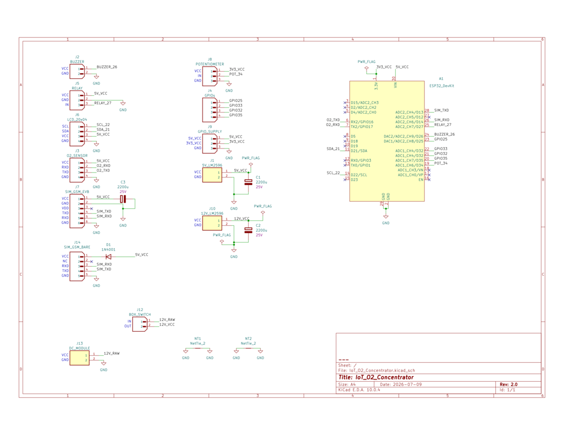
Full wiring, schematic, and PCB layout are documented in docs/.
project-root/
├── firmware/               # Arduino sketch (.ino), config.h, portal_html.h
├── hardware/                # KiCad schematic, PCB layout, Gerber files
├── docs/                    # Full project documentation, diagrams, images
├── README.md                # This file
├── SETUP.md                 # Step-by-step setup guide for Arduino IDE
└── .gitignoreThe system escalates through five tiers based on O2 purity. Only the DANGER tier and above place a voice call; only WARNING sends SMS. The compressor keeps running through every tier except CRITICAL — the design assumes a caregiver may not respond immediately, so oxygen delivery is only stopped once purity has effectively fallen to ambient air levels, at which point the compressor was providing no therapeutic value anyway.
| Tier | O2 Purity | Buzzer | Caregiver Contact | Relay |
|---|---|---|---|---|
| NORMAL | ≥ 85% | Silent | — | ON |
| WARNING | 70% – 85% | Single beep, 1s cycle | SMS | ON |
| DANGER | 35% – 70% | Double beep, 1s cycle | Voice call | ON |
| SEVERE | 23% – 35% | Continuous tone | Voice call | ON |
| CRITICAL | < 23% (3 consecutive readings) | Continuous tone | Voice call | OFF |
Thresholds are runtime-adjustable (see Configuration below)
and persist in NVS flash. Default fallback values live in firmware/config.h.
All alerts are suppressed for 30 seconds after boot to allow the sensor warm-up and GSM network registration to settle before any buzzer, SMS, or call can fire.
The system supports three interchangeable data sources, switchable at any time from the web portal without reflashing:
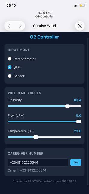
WiFi captive portal for demo input and caregiver configuration
The firmware uses FreeRTOS (built into the ESP32 Arduino core — no extra install needed). Five tasks run concurrently, sharing data through two mutex-protected resources:
| Task | Core | Responsibility |
|---|---|---|
sensorTask | 0 | Reads active input mode (pot / WiFi / sensor), updates shared O2 data |
displayTask | 0 | Updates all 4 rows of the LCD every 500 ms |
webTask | 0 | Hosts the WiFi AP, captive portal, and DNS redirect |
gsmTask | 1 | Initialises modem on boot, monitors network registration every 5s |
configTask | 1 | Handles USB serial and incoming SMS configuration commands |
alertTask | 1 (highest priority) | Evaluates the 5-tier state machine, drives buzzer/relay/SMS/call |
dataMutex protects the shared sensor reading; modemMutex protects all TinyGSM AT command calls,
since multiple tasks share the same SIM800L UART.
See SETUP.md for the full step-by-step setup guide.
firmware/IoT_O2_Concentrator.inoThree interchangeable ways to configure the system — all write to the same NVS storage:
1. Web portal (easiest, works in any input mode)
Connect to WiFi network O2-Controller (password 12345678), a captive portal should
open automatically. Enter the caregiver number in the "Caregiver Number" card and tap Set.
2. USB Serial (115200 baud)
SET NUM +2348012345678
SET WARN 72
SET NORM 87
STATUS
HELP
3. SMS to the device SIM Send the same commands as SMS text to the SIM card installed in the SIM800L EVB. The device replies with confirmation and deletes the processed message.
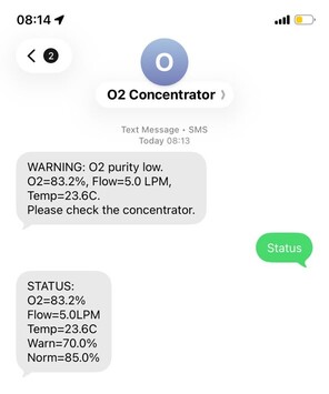
Caregiver receiving a live SMS alert
All three methods are always available regardless of which input mode (pot/WiFi/sensor) is active.
Full design documentation is in the docs/ folder. It covers:
Project by Smart Ayodele. README last updated to match firmware Rev 1.4
| Qty | Value | Footprint | References |
|---|---|---|---|
| 3 | 2200u | Capacitor_THT:C_Radial_D10.0mm_H12.5mm_P5.00mm | C1, C2, C3 |
| 2 | NetTie_2 | PCM_SL_Jumpers:JUP_P10mm | NT1, NT2 |
| 1 | 1N4001 | Diode_THT:D_DO-41_SOD81_P10.16mm_Horizontal | D1 |
| 1 | BOX_SWITCH | footprint:JST_B2B-XH-A | J12 |
| 1 | BUZZER | footprint:JST_B2B-XH-A | J2 |
| 1 | DC_MODULE | footprint:TB002-500-02BE | J13 |
| 1 | ESP32_DevKit | PCM_SL_Development_Boards:DOIT_ESP32_DEVKIT_30Pins | A1 |
| 1 | GPIO_SUPPLY | footprint:JST_B3B-XH-A | J9 |
| 1 | GPIOs | footprint:JST_B4B-XH-A | J4 |
| 1 | LCD_20x04 | footprint:JST_B4B-XH-A | J6 |
| 1 | LM2596_IN | footprint:TB002-500-02BE | J10 |
| 1 | LM2596_OUT | footprint:TB002-500-02BE | J1 |
| 1 | O2_SENSOR | footprint:JST_B4B-XH-A | J3 |
| 1 | POTENTIOMETER | footprint:JST_B3B-XH-A | J8 |
| 1 | RELAY | footprint:JST_B3B-XH-A | J5 |
| 1 | SIM_GSM_BARE | footprint:JST_B5B-XH-A | J14 |
| 1 | SIM_GSM_EVB | footprint:JST_B6B-XH-A | J7 |


axlan/pcb-map
PCB designs, firmware, and host SW for controlling an interactive map printed onto a PCB board.

badges4dotcom/bsidesperth2025badge
Instructions on how to assemble the physical badge can be found here


ronaldsieber/ESP32SmartBoard_PCB
KiCad project of a Printed Cuircit Board (PCB) for ESP32 with Temperature/Humidity/CO2 Sensors, User LEDs and Buttons

cristianghsandu/edifier-remote
An ESP32 based IR signals translator to use the LG Magic remote to control the volume on an Edifier 2.1 system

Pendu1699/solar-mppt-charge-controller
ESP32-based solar MPPT charge controller, custom PCB, perturb & observe tracking algorithm, logged efficiency test data.
It measures 110 × 82 mm and has 2 copper layers, 1.6 mm thick.
20 parts, built around the ESP32-DEVKITM-1. The full list of its parts is on this page, with links to each part's symbol and footprint where PCBKit's library has them.
From the BigSmartt01/IoT_O2_Concentrator repository on GitHub, at the commit this page was made from: the board is hardware/IoT_O2_Concentrator.kicad_pcb and its schematic hardware/IoT_O2_Concentrator.kicad_sch. PCBKit opens the board in the browser, with nothing to install.
Its repository states no licence, so its author keeps all rights: ask BigSmartt01 before reusing the design.