2 layers40 × 22.8 mm

 BD5HLI/DigiPort15
集成USB口和声卡的业余电台数据模式接口盒子
Digiport-891 is an open-source printed circuit board by BD5HLI, from the BD5HLI/DigiPort repository on GitHub, published under the GPL-3.0 licence. It is a 2-layer board of 40 × 22.8 mm with 45 parts on 72 nets, routed with 366 tracks and 30 vias.
It is built around the CM108B, USB2412-DZK-TR and GS2005ELD, with the MMBT5551L and PJ-320A among its other parts. Its parts include 17 resistors, 16 capacitors, 3 connectors, 2 ICs and 2 diodes.


面向八重洲FT-891的FT8模式集成接口,内置一个2口的USB2.0 HUB和一个USB声卡,通过一个Type-C接口连接电脑或者手机,解决FT-891没有内置声卡的问题。
本项目采用了Digirig-Mobile项目(https://github.com/softcomplex/Digirig-Mobile )的符号库、封装库和3D器件模型,参考了Digirig DR-891的原理图(https://digirig.net/digirig-dr-891-setup-manual/ )设计,精简了几乎用不到的CM108B GPIO脚的PTT功能,保留了VOX-PTT功能。此外,本项目的被动器件(电阻、电容)均采用0402手焊封装,便于手工焊接。
本项目虽然面向FT-891设计,实际上可以仅使用USB声卡的功能,从而适用于绝大多数带有音频输入输出接口的电台,比如K5、K6手台,配合相应的软件可以实现SSTV、APRS等玩法。
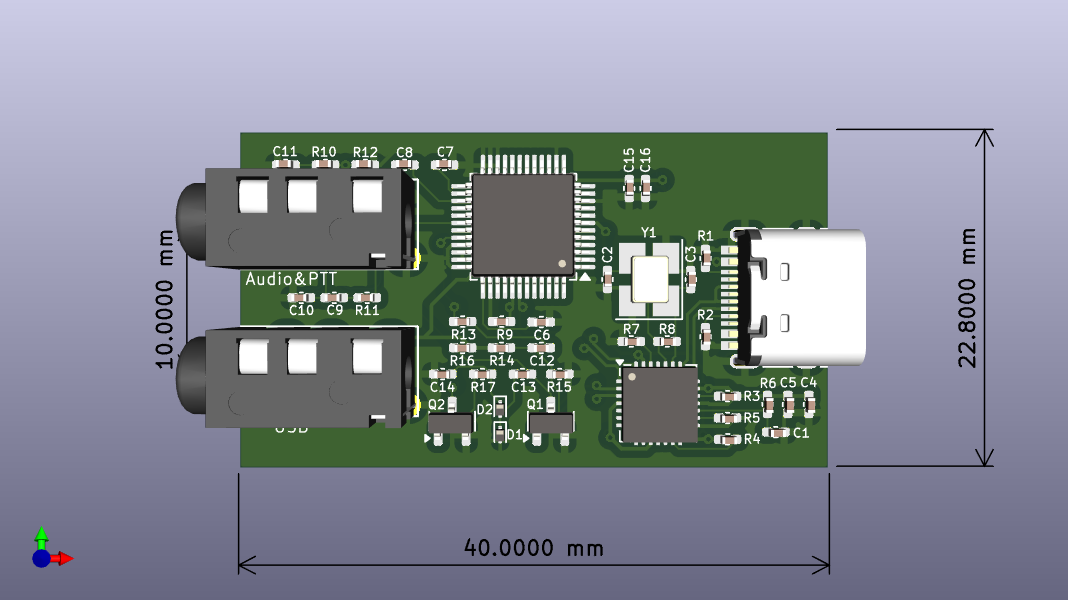
电路板正面:
电路板反面:
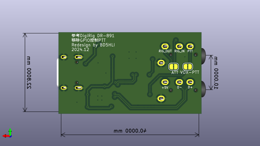
DigiPort在电脑侧的接口为type c接口,可使用c to a或c to c数据线连接电脑或者手机;在电台侧的接口包括两个3.5mm的4芯TRRS接口,面向电路板器件面、type c接口在右侧时,左上的TRRS接口为音频/PTT接口,左下的TRRS接口为USB接口。
DigiPort的音频/PTT接口定义如下:
   /\
  |  |---------> 尖端   RIG_AFOUT 电台音频输出,接FT-891 DATA口的DATA OUT脚
  |--|
  |  |---------> 第一环 RIG_AFIN  电台音频输入,接FT-891 DATA口的DATA IN脚
  |--|
  |  |---------> 第二环 VOX_PTT   声控PTT,接FT-891 DATA口的PTT脚
  |--|
  |  |---------> 底部   GND       信号地,接FT-891 DATA口的GND脚
__|  |__
|      |
VOX_PTT信号用于没有USB串口的设备控制收发转换,控制源来自CM108B声卡的右声道,推荐采用1kHz或2kHz的单音作为VOX触发信号。
FT-891的DATA插座定义如下:
    /-----\      1脚:DATA IN
   / 6 _ 5 \     2脚:GND
  |4  |_|  3|    3脚:PTT
   \ 2   1 /     4脚:SHIFT
    \-----/      5脚:DATA OUT
                 6脚:SQL
DigiPort的电台侧USB接口定义如下:
   /\
  |  |---------> 尖端   +5V 电台USB口的+5V电源脚
  |--|
  |  |---------> 第一环 D-  电台USB口的D-脚
  |--|
  |  |---------> 第二环 D+  电台USB口的D+脚
  |--|
  |  |---------> 底部   GND 电台USB口的GND脚
__|  |__
|      |
USB Type-B插头定义如下:
   /-+=+--+=+-\     1脚:+5V
  /  |=|  |=|  \
  |   1    2   |    2脚:D-
  |            |
  |   4    3   |    3脚:D+
  |  |=|  |=|  |
|--+=+--+=+--| 4脚:GND 感谢LX6FB提供原版DR-891的照片。
感谢BG5ARO对端板设计提出了宝贵建议,并提供了CNC加工。
感谢BG5BQB提供了3D打印工艺的端板原型样件。
| Qty | Value | Footprint | References |
|---|---|---|---|
| 6 | 10uF | Capacitor_SMD:C_0402_1005Metric_Pad0.74x0.62mm_HandSolder | C4, C6, C7, C8, C9, C15 |
| 5 | 100K | Capacitor_SMD:C_0402_1005Metric_Pad0.74x0.62mm_HandSolder | R3, R4, R5, R6, R10 |
| 3 | 100nF | Capacitor_SMD:C_0402_1005Metric_Pad0.74x0.62mm_HandSolder | C1, C5, C16 |
| 3 | 10K | Capacitor_SMD:C_0402_1005Metric_Pad0.74x0.62mm_HandSolder | R7, R12, R14 |
| 3 | 1K5 | Capacitor_SMD:C_0402_1005Metric_Pad0.74x0.62mm_HandSolder | R9, R16, R17 |
| 3 | 1uF | Capacitor_SMD:C_0402_1005Metric_Pad0.74x0.62mm_HandSolder | C12, C13, C14 |
| 2 | 1nF | Capacitor_SMD:C_0402_1005Metric_Pad0.74x0.62mm_HandSolder | C10, C11 |
| 2 | 22 | Capacitor_SMD:C_0402_1005Metric_Pad0.74x0.62mm_HandSolder | R11, R13 |
| 2 | 27pF | Capacitor_SMD:C_0402_1005Metric_Pad0.74x0.62mm_HandSolder | C2, C3 |
| 2 | 5K1 | Capacitor_SMD:C_0402_1005Metric_Pad0.74x0.62mm_HandSolder | R1, R2 |
| 2 | GS2005ELD | Diode_SMD:D_SOD-923 | D1, D2 |
| 2 | MMBT5551L | Package_TO_SOT_SMD:SOT-23 | Q1, Q2 |
| 2 | PJ-320A | footprints:TRRS-PJ-320A | J2, J3 |
| 1 | 1M | Capacitor_SMD:C_0402_1005Metric_Pad0.74x0.62mm_HandSolder | R8 |
| 1 | 24MHz | Crystal:Crystal_SMD_3225-4Pin_3.2x2.5mm_HandSoldering | Y1 |
| 1 | 2K0 | Capacitor_SMD:C_0402_1005Metric_Pad0.74x0.62mm_HandSolder | R15 |
| 1 | ATT | Jumper:SolderJumper-2_P1.3mm_Bridged2Bar_RoundedPad1.0x1.5mm | JP1 |
| 1 | CM108B | Package_QFP:LQFP-48_7x7mm_P0.5mm | U2 |
| 1 | USB2412-DZK-TR | Package_DFN_QFN:QFN-28-1EP_5x5mm_P0.5mm_EP3.35x3.35mm | U1 |
| 1 | USB_C_Receptacle_USB2.0_16P | footprints:USB_C_Receptacle_HRO_TYPE-C-31-M-12 | J1 |
| 1 | VOX | Jumper:SolderJumper-2_P1.3mm_Bridged2Bar_RoundedPad1.0x1.5mm | JP2 |

softcomplex/Digirig-Mobile
Integrated digital modes interface for amateur radio

softcomplex/Digirig-Lite
Minimalistic CM108B-based digital modes interface for ham radio


AndreaGiulianini/lira
57-key 40% + numpad keyboard: Bluetooth/USB-C, hot-swap MX, RMK/Vial, and a built-in USB sound card (3.5 mm headset jack). Generated from source with KiCad.


It measures 40 × 22.8 mm and has 2 copper layers, 1.6 mm thick.
45 parts, built around the CM108B, USB2412-DZK-TR, GS2005ELD and MMBT5551L. The full list of its parts is on this page, with links to each part's symbol and footprint where PCBKit's library has them.
From the BD5HLI/DigiPort repository on GitHub, at the commit this page was made from: the board is digiport-891/digiport-891.kicad_pcb and its schematic digiport-891/digiport-891.kicad_sch. PCBKit opens the board in the browser, with nothing to install.
Its repository publishes it under the GPL-3.0 licence: you may reuse it on that licence's terms (keep the author's notice, and for a copyleft licence share your changes alike).