
2 layers100 × 60 mm

 Autonomous-Motorsports-Purdue/AMP_PCB_Brake-Controller
PCB with brake motor controller files and documentation
Brake Controller is an open-source printed circuit board by Autonomous-Motorsports-Purdue, from the Autonomous-Motorsports-Purdue/AMP_PCB_Brake-Controller repository on GitHub. It is a 2-layer board of 35.6 × 38.1 mm with 28 parts on 19 nets, routed with 134 tracks and 24 vias.
It is built around the IFX007T. Its parts include 11 capacitors, 9 resistors, 2 ICs, 2 connectors and 1 diode. It belongs with the robots and motor control boards of this library.
PCB with brake motor controller files and documentation
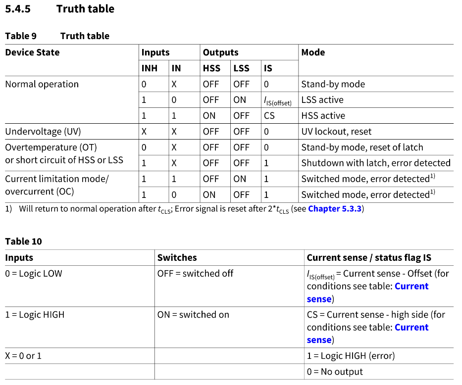
Operation truth table:
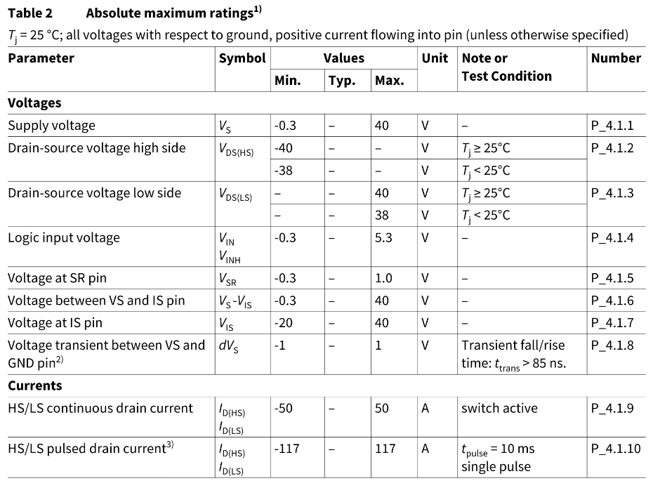
Absolute maximum ratings:
| Qty | Value | Footprint | References |
|---|---|---|---|
| 5 | 10K | Resistor_SMD:R_0805_2012Metric_Pad1.20x1.40mm_HandSolder | R1, R12, R13, R22, R23 |
| 4 | 220nF | Capacitor_SMD:C_0805_2012Metric_Pad1.18x1.45mm_HandSolder | C1, C2, C3, C4 |
| 2 | 100nF | Capacitor_SMD:C_0805_2012Metric_Pad1.18x1.45mm_HandSolder | C5, C6 |
| 2 | 10nF | Capacitor_SMD:C_0805_2012Metric_Pad1.18x1.45mm_HandSolder | C15, C25 |
| 2 | 1K | Resistor_SMD:R_0805_2012Metric_Pad1.20x1.40mm_HandSolder | R15, R25 |
| 2 | 1nF | Capacitor_SMD:C_0805_2012Metric_Pad1.18x1.45mm_HandSolder | C14, C24 |
| 2 | 500 | Resistor_SMD:R_0805_2012Metric_Pad1.20x1.40mm_HandSolder | R14, R24 |
| 2 | IFX007T | Package_TO_SOT_SMD:TO-263-7_TabPin4 | U1, U2 |
| 1 | 1000uF | Capacitor_SMD:C_0805_2012Metric_Pad1.18x1.45mm_HandSolder | C7 |
| 1 | 10V | Package_TO_SOT_SMD:SOT-23 | D1 |
| 1 | INPUT | Connector_PinHeader_2.54mm:PinHeader_1x13_P2.54mm_Vertical | J1 |
| 1 | LOGO | assets:Logo | G*** |
| 1 | OUTPUT | Connector_PinHeader_2.54mm:PinHeader_1x13_P2.54mm_Vertical | J2 |
| 1 | Protection bypass | Jumper:SolderJumper-2_P1.3mm_Open_TrianglePad1.0x1.5mm | JP1 |
| 1 | Q_PMOS_GDS | Package_TO_SOT_SMD:TO-252-2 | Q1 |


trainman419/dccpp_pcb
This is the DCC++ board project. It's a relatively simple printed circuit board which integrates all of the components that are necessary for a DCC++ base station onto a single PCB, with all of the things you need, and…


joeycastillo/Sensor-Watch
A board replacement for the classic Casio F-91W wristwatch

TalismanDesign/PocketMage_PDA
An E-Ink PDA device using the ESP32 S3.

rusefi/rusefi
rusefi - GPL internal combustion engine control unit

hackclub/OnBoard
💡 Join 1,000 teenagers and make your first PCB with a $100 grant!
It measures 35.6 × 38.1 mm and has 2 copper layers, 1.6 mm thick.
28 parts, built around the IFX007T. The full list of its parts is on this page, with links to each part's symbol and footprint where PCBKit's library has them.
From the Autonomous-Motorsports-Purdue/AMP_PCB_Brake-Controller repository on GitHub, at the commit this page was made from: the board is Brake Controller.kicad_pcb and its schematic Brake Controller.kicad_sch. PCBKit opens the board in the browser, with nothing to install.
Its repository states no licence, so its author keeps all rights: ask Autonomous-Motorsports-Purdue before reusing the design.