

2 layers225 × 80 mm
VFD
davidmpye/VFD
This repository contains a design for an IV-11 based Vacuum Fluorescent Display (VFD) display unit.
72 parts9

 AronASzucs/IV-11-VFD-Clock43
6-digit Soviet IV-11 VFD tube clock — custom PCB, mixed 25V/1.5V power system, 7-state FSM firmware
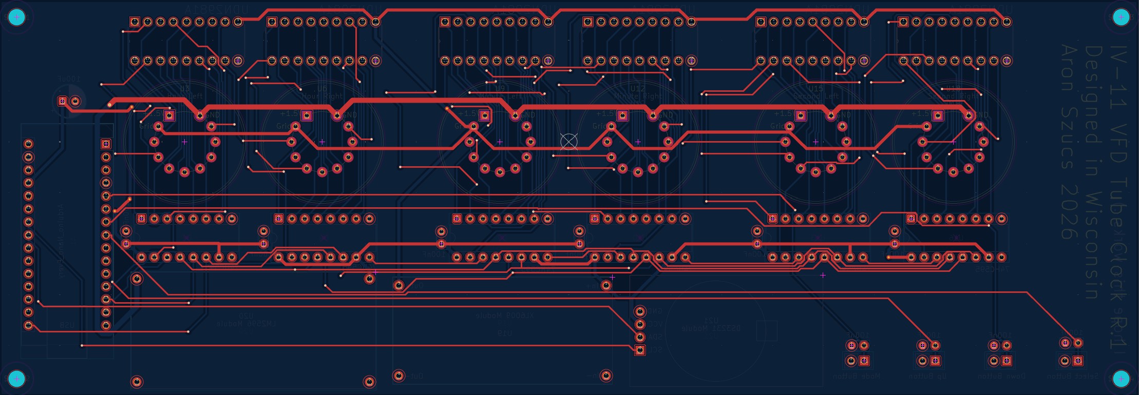
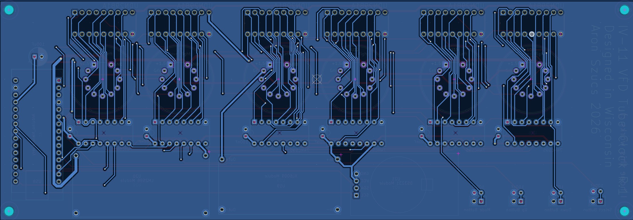
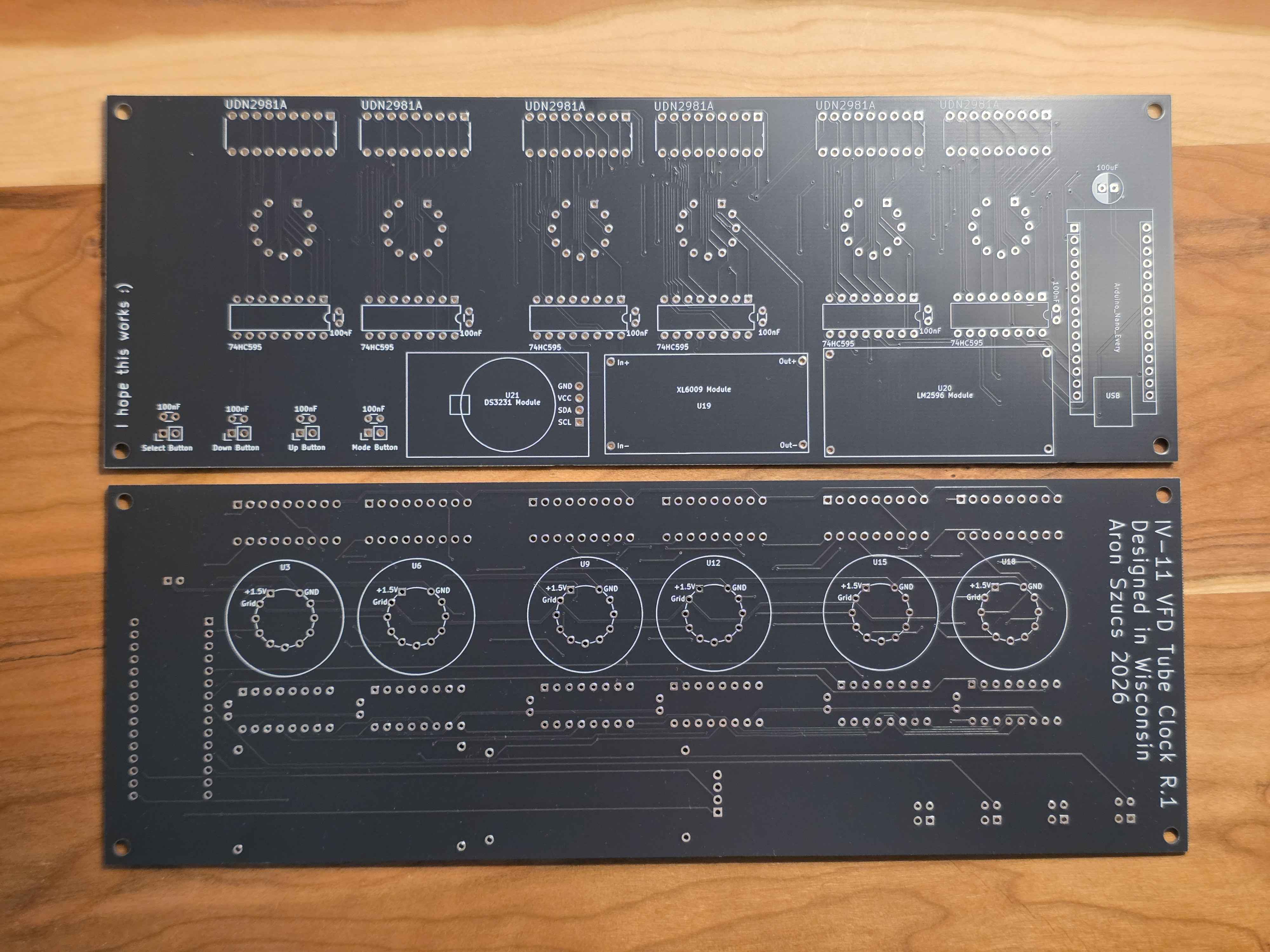
VFD Clock is an open-source printed circuit board by AronASzucs, from the AronASzucs/IV-11-VFD-Clock repository on GitHub. It is a 2-layer board of 224 × 78 mm with 41 parts on 133 nets, routed with 1,228 tracks and 93 vias.
It is built around the UDN2981A-T and 74HC595. Its parts include 21 ICs, 11 capacitors and 4 connectors. It belongs with the lEDs and displays boards and the AVR (ATmega, ATtiny) boards of this library.
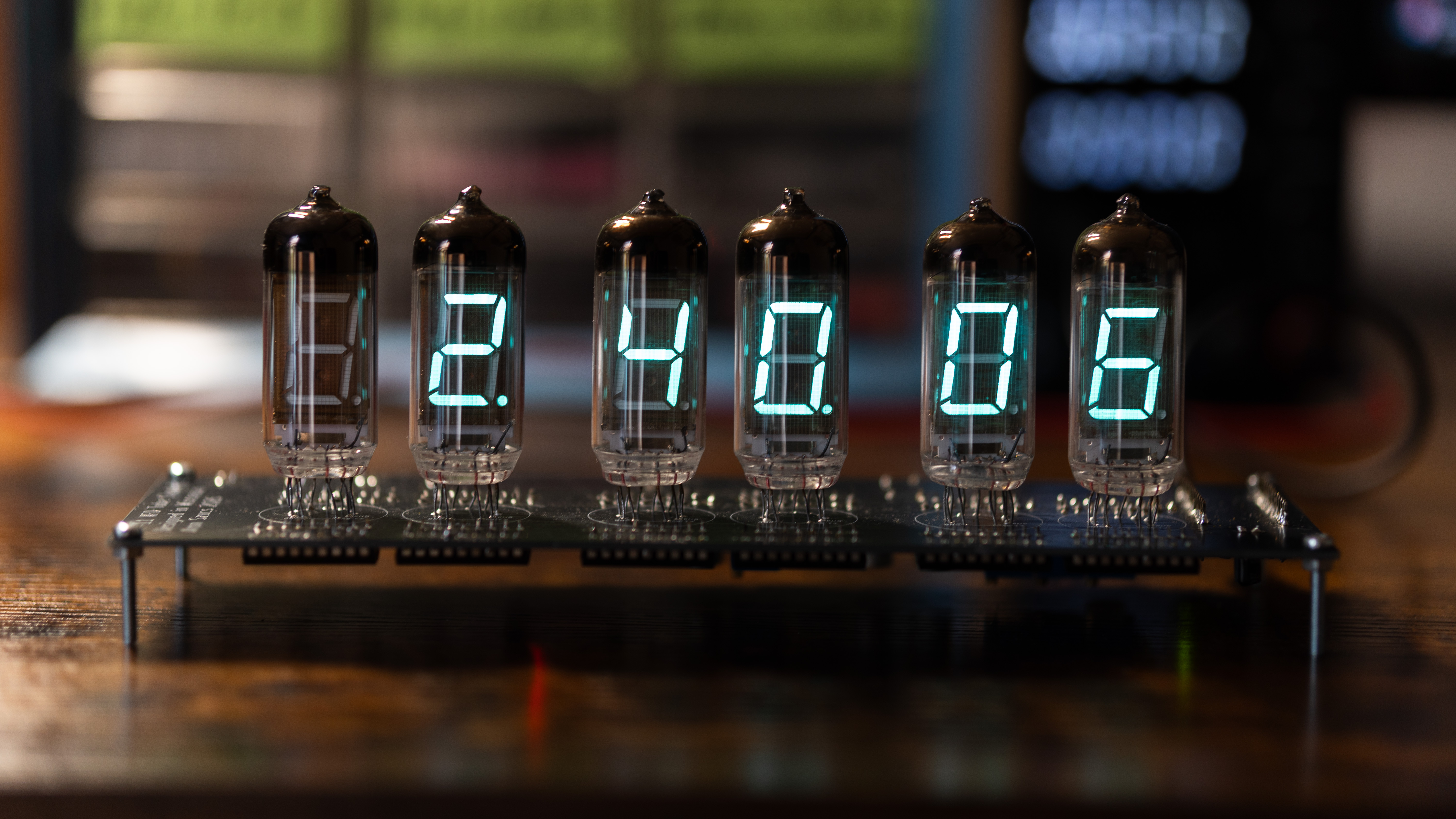
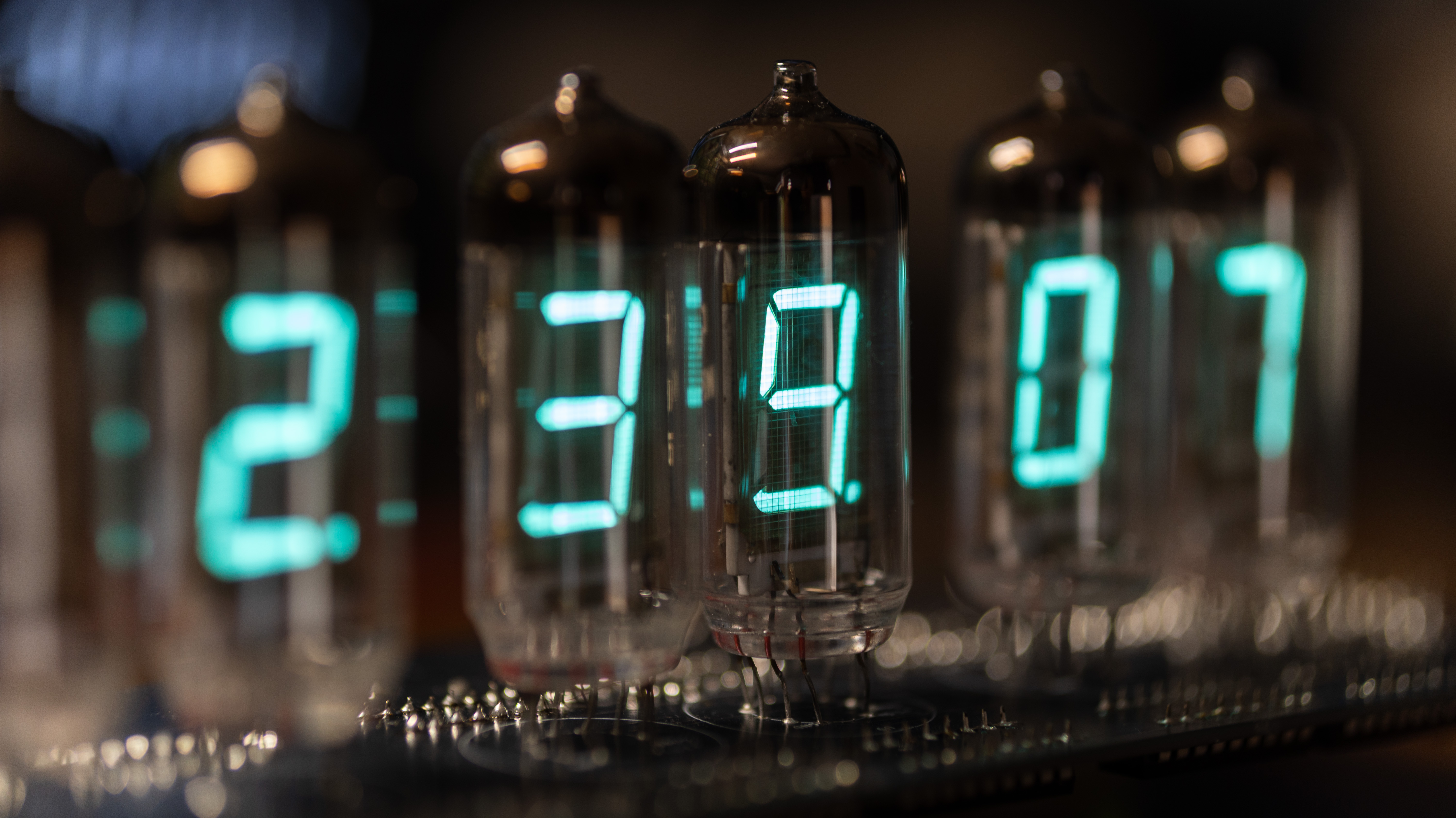
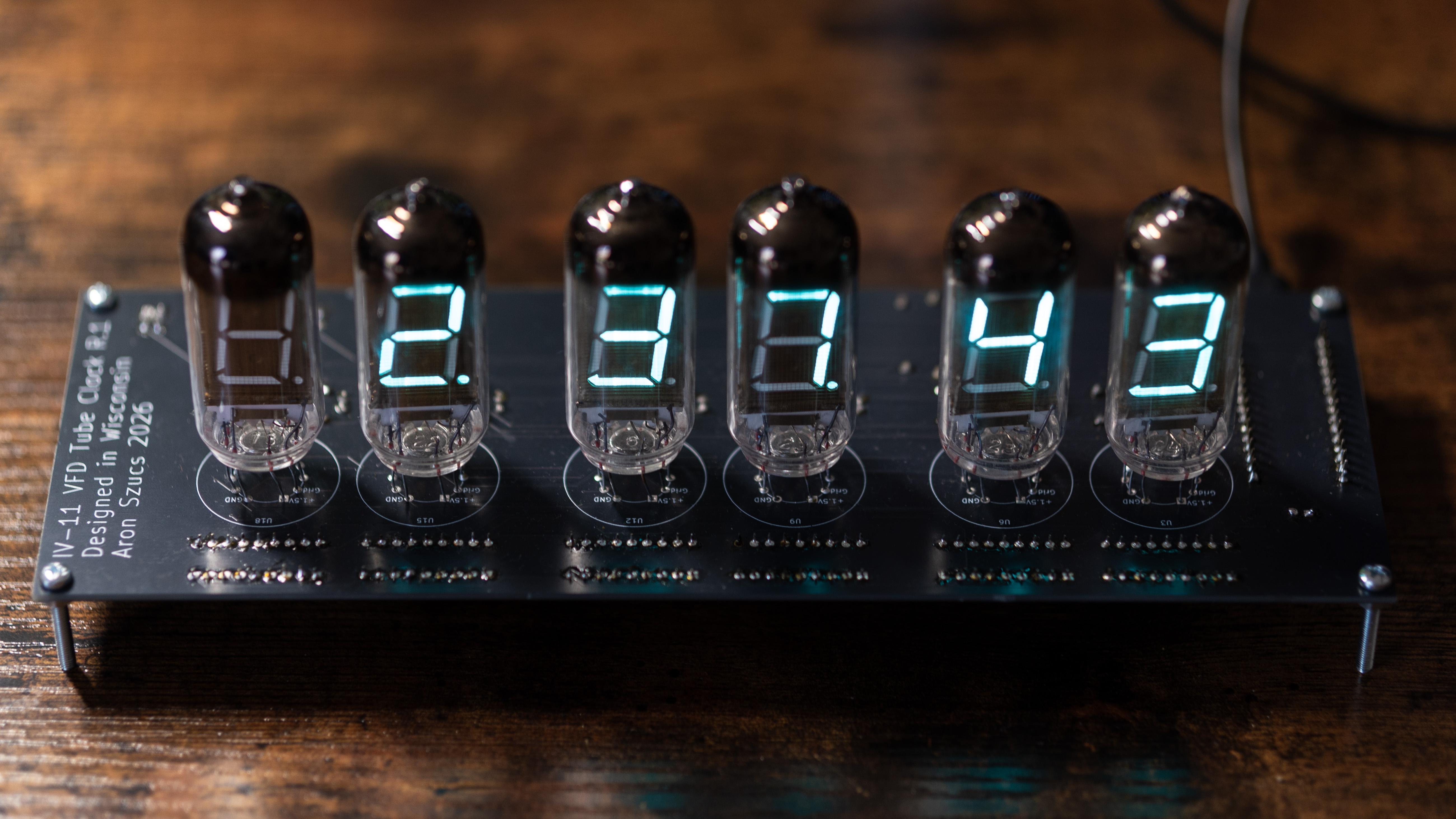
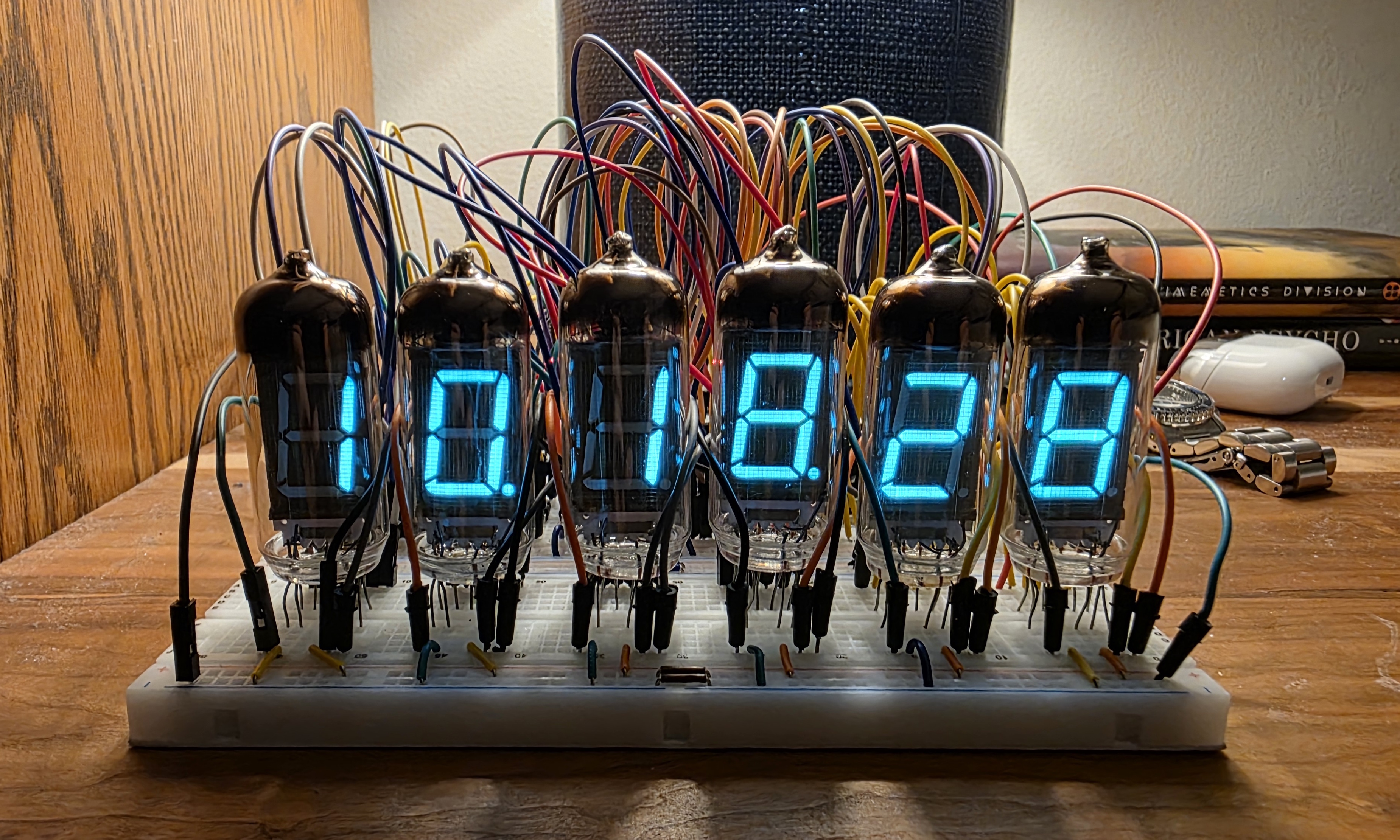
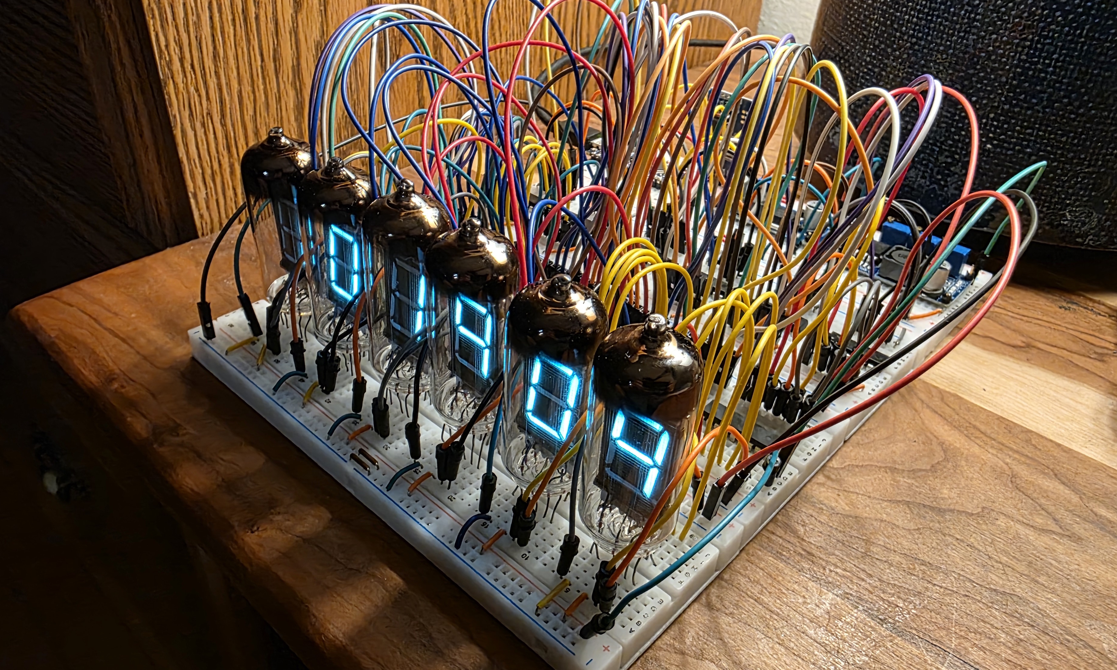
A 6-digit clock built around Soviet-era IV-11 vacuum fluorescent display tubes, vintage components manufactured in Ukraine during the 1970s-80s. The entire project was designed from scratch, including schematic design, custom PCB layout, and firmware, with no kit or reference design used beyond architectural inspiration.
Display 6x IV-11 7-segment VFD tubes driven in a static configuration. One dedicated 74HC595N shift register and UDN2981A high-voltage source driver per tube, all daisy-chained via SPI. Static drive means every tube is on simultaneously at full brightness with no multiplexing.
Power Supply The clock runs entirely from a 5V USB source with two onboard switching converters:
Timekeeping DS3231 real-time clock module over I2C with CR2032 battery backup. Accurate to ±2ppm and loses less than one minute per year.
Microcontroller Arduino Nano Every handling SPI display control, I2C RTC communication, PWM brightness via shift register OE pin, button input with hardware debounce, and EEPROM-persistent user settings.
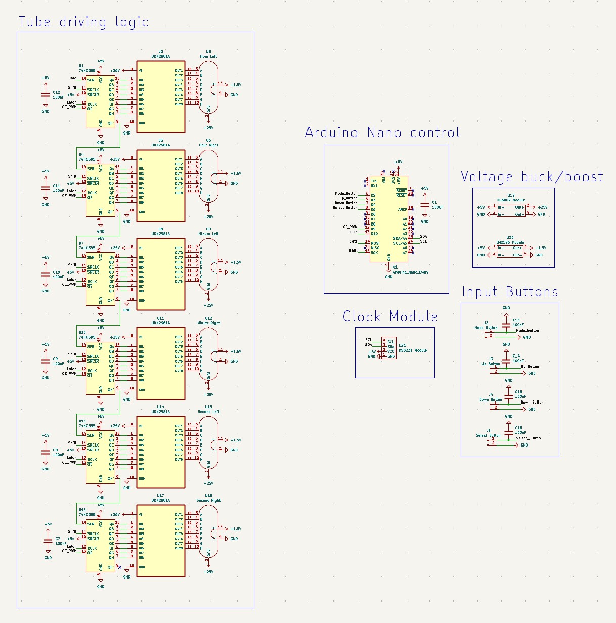
The clock firmware implements a 7-state FSM for all user interaction:
| Mode | Function |
|---|---|
| 0 | Normal clock display |
| 1 | Set hours |
| 2 | Set minutes |
| 3 | Set seconds |
| 4 | Manual brightness (1–9) |
| 5 | Auto-brightness on/off |
| 6 | 12/24hr toggle |
Features include PWM brightness control via the 74HC595 OE pin, automatic-brightness scheduling by hour of day, hardware debounce capacitors on all button inputs, and full EEPROM persistence for brightness, auto-brightness, and 12/24hr preference across power cycles.
2-layer board designed in KiCad, fabricated by JLCPCB. Custom symbols and footprints created for the IV-11 tubes, XL6009 boost converter, and LM2596 buck converter modules. Ground plane on the bottom copper layer. Power traces sized for current capacity: 1.0mm for the 600mA filament rail and 0.5mm for the 25V anode rail.
Gerbers folder.| Component | Source | Cost |
|---|---|---|
| IV-11 tubes × 6 | eBay | $40.09 |
| PCB × 5 | JLCPCB | $22.84 |
| Buttons × 6 | AliExpress | $6.93 |
| Screws and hex nuts | Hardware Store | $6.25 |
| UDN2981A × 10 | AliExpress | $3.39 |
| XL6009 modules × 3 | AliExpress | $2.99 |
| DS3231 RTC module | AliExpress | $2.19 |
| LM2596 modules × 2 | AliExpress | $1.59 |
| 74HC595N × 10 | AliExpress | $1.19 |
| Arduino Nano Every | University | Free |
| Capacitors, resistors, headers | University | Free |
| Total | $87.46 |
Inspired by OpenVFD for the static drive architecture using 74HC595 shift registers and UDN2981A source drivers.
| Qty | Value | Footprint | References |
|---|---|---|---|
| 10 | 100nF | Capacitor_THT:C_Disc_D3.0mm_W1.6mm_P2.50mm | C7, C8, C9, C10, C11, C12, C13, C14, C15, C16 |
| 6 | 74HC595 | Package_DIP:DIP-16_W7.62mm | U1, U4, U7, U10, U13, U16 |
| 6 | UDN2981A | UDN2981A:DIP254P762X533-18 | U2, U5, U8, U11, U14, U17 |
| 4 | MountingHole_3.2mm_M3 | MountingHole:MountingHole_3.2mm_M3 | Hole1, Hole2, Hole3, Hole4 |
| 1 | 100uF | Capacitor_THT:CP_Radial_D6.3mm_P2.50mm | C1 |
| 1 | Arduino_Nano_Every | Module:Arduino_Nano | A1 |
| 1 | DS3231 Module | Custom Parts:DS3231 Module | U21 |
| 1 | Down Button | Connector_PinHeader_2.54mm:PinHeader_1x02_P2.54mm_Vertical | J4 |
| 1 | Hour Left | Custom Parts:IV-11 VFD Tube | U3 |
| 1 | Hour Right | Custom Parts:IV-11 VFD Tube | U6 |
| 1 | LM2596 Module | Custom Parts:LM2596 Module | U20 |
| 1 | Minute Left | Custom Parts:IV-11 VFD Tube | U9 |
| 1 | Minute Right | Custom Parts:IV-11 VFD Tube | U12 |
| 1 | Mode Button | Connector_PinHeader_2.54mm:PinHeader_1x02_P2.54mm_Vertical | J2 |
| 1 | Second Left | Custom Parts:IV-11 VFD Tube | U15 |
| 1 | Second Right | Custom Parts:IV-11 VFD Tube | U18 |
| 1 | Select Button | Connector_PinHeader_2.54mm:PinHeader_1x02_P2.54mm_Vertical | J5 |
| 1 | Up Button | Connector_PinHeader_2.54mm:PinHeader_1x02_P2.54mm_Vertical | J3 |
| 1 | XL6009 Module | Custom Parts:XL6009 Module | U19 |
davidmpye/VFD
This repository contains a design for an IV-11 based Vacuum Fluorescent Display (VFD) display unit.

jamesfowkes/cryptology-countdown
PCBs and software for two synchronous countdown timers

ra0sms/universal_control_console
Control console for any types of antenna's switches

Sutthiphong-H/project-flip-disc
FlipDisc Project was made for education of Project. Chadsadakorn Piriyasiriphan Jadesalit Suriyanimitsuk Sutthiphong Hongkham

CatoLynx/LAWO-Arduino
Arduino Nano adapter board for LAWO XY5 flipdot displays

Qeteshpony/Flipdot-Controller
Replacement controller for a Lawo Luminator Flipdot Display


It measures 224 × 78 mm and has 2 copper layers, 1.6 mm thick.
41 parts, built around the UDN2981A-T and 74HC595. The full list of its parts is on this page, with links to each part's symbol and footprint where PCBKit's library has them.
From the AronASzucs/IV-11-VFD-Clock repository on GitHub, at the commit this page was made from: the board is VFD Clock.kicad_pcb and its schematic VFD Clock.kicad_sch. PCBKit opens the board in the browser, with nothing to install.
Its repository states no licence, so its author keeps all rights: ask AronASzucs before reusing the design.