
2 layers83.3 × 65.3 mm
SimonShield
github-linguist/linguist
Language Savant. If your repository's language is being reported incorrectly, send us a pull request!
46 parts14kMIT
 Armaan240/PIKASOLDER
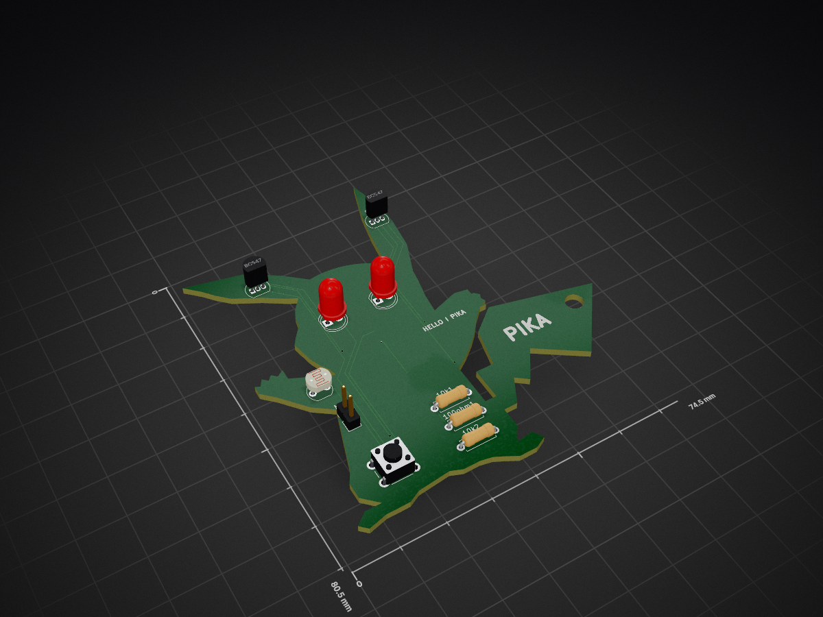
⚡ Pikachu PCB: Auto LED & Motor Circuit A Pikachu-shaped PCB that lights up LEDs in the dark using an LDR and turns on both LEDs and a vibration motor when a button is pressed in daylight. Powered by a CR2032 coin cell and controlled via a BC547 transistor.
PCBBOARD is an open-source printed circuit board by Armaan240, from the Armaan240/PIKASOLDER repository on GitHub. It is a 2-layer board of 74.5 × 80.5 mm with 12 parts on 7 nets, routed with 91 tracks and 7 vias.
It is built around the BC547. Its parts include 2 transistors, 1 resistor, 1 diode, 1 switch and 1 inductor.
⚡ Pikachu PCB: Auto LED & Motor Circuit A Pikachu-shaped PCB that lights up LEDs in the dark using an LDR and turns on both LEDs and a vibration motor when a button is pressed in daylight. Powered by a CR2032 coin cell and controlled via a BC547 transistor.
Single-Button Control (Keychain Switch):
Automatic Light Sensor (Optional LDR Mode):
Compact Design:
Powered by a small battery (e.g., coin cell or 3V CR2032) for portability.
Images of The Project


| # | Part Name | Label | Value/Type | Package / Footprint | Qty |
|---|---|---|---|---|---|
| 1 | NPN Transistor | Q1 ,Q2 | BC547 | TO-92 (TO-92_Inline) | 2 |
| 2 | Light Dependent Resistor | LDR | GL5528 (typical) | Resistor_THT:R-2.5 (or similar photoresistor pad) | 1 |
| 3 | Resistor | R1 | 10kΩ | R_Axial_DIN0207_L6.3mm_P7.62mm_Horizontal | 2 |
| 4 | Resistor | R2 | 100Ω – 470Ω | Same as above | 1 |
| 5 | Red LED | L1 | 5mm LED | LED_THT:LED_D5.0mm | 1 |
| 6 | Red LED | L2 | 5mm LED | LED_THT:LED_D5.0mm | 1 |
| 7 | Tactile Push Button | SW1 | 6x6 mm Push Button | Button_Switch_THT:SW_PUSH_6mm_H5mm | 1 |
| 8 | Coin Vibration Motor | M1 | 3V Vibration Motor | Connected via header (Conn_01x02_Male) | 1 |
| 9 | Coin Cell Battery Holder | BT1 | CR2032 Holder | Battery_Holder_Keystone_3002_1x20mm | 1 |
| 10 | Generic Header (Motor Pads) | J1 | 2-pin male header | Conn_01x02_Male or TestPoints | 1 |
Would you like me to export this BoM in .csv or .xlsx format ready for JLCPCB/assembly quoting?
+VCC, GND) to avoid messy wires.| Qty | Value | Footprint | References |
|---|---|---|---|
| 3 | R1 | Resistor_THT:R_Axial_DIN0207_L6.3mm_D2.5mm_P7.62mm_Horizontal | 10k1, 10k2, 100ohm1 |
| 2 | BC547 | Package_TO_SOT_THT:TO-92_Inline | Q1, Q2 |
| 1 | Battery_Cell | Battery:BatteryHolder_Keystone_3002_1x2032 | BT1 |
| 1 | L2 | LED_THT:LED_D5.0mm | D2 |
| 1 | LDR | OptoDevice:R_LDR_5.0x4.1mm_P3mm_Vertical | R1 |
| 1 | LED | LED_THT:LED_D5.0mm | L1 |
| 1 | Motor | Connector_PinHeader_2.54mm:PinHeader_1x02_P2.54mm_Vertical | M2 |
| 1 | SW_Push | Button_Switch_THT:SW_PUSH_6mm_H5mm | SW2 |
The 11 most common of 12 parts.
github-linguist/linguist
Language Savant. If your repository's language is being reported incorrectly, send us a pull request!

dotnet/iot
This repo includes .NET Core implementations for various IoT boards, chips, displays and PCBs.

peterheinrich/InternetOverSpaghetti
Transmitting IP packages over a pair of spaghetti thus demonstrating how media independent IP really is.

tebl/RC6502-Apple-1-Replica
An expandable SBC-version of the Apple 1 computer, easy to get started with and lot of cool stuff that can be added to it!


ZeroPhone/ZeroPhone-PCBs
PCB files for ZeroPhone - for gerbers and schematics, go to "Releases" tab!

It measures 74.5 × 80.5 mm and has 2 copper layers, 1.6 mm thick.
12 parts, built around the BC547. The full list of its parts is on this page, with links to each part's symbol and footprint where PCBKit's library has them.
From the Armaan240/PIKASOLDER repository on GitHub, at the commit this page was made from: the board is PCBBOARD.kicad_pcb and its schematic SCHEMATIC.kicad_sch. PCBKit opens the board in the browser, with nothing to install.
Its repository states no licence, so its author keeps all rights: ask Armaan240 before reusing the design.