4 layers28 × 52 mm
BT MacroPad Before PajoPCB
AntranigB/BT-MacroPad
All of these make it hard to handle keyboard, especially from afar. BUT what if while you're doing those you want to:
21 parts

 AntranigB/BT-MacroPad
All of these make it hard to handle keyboard, especially from afar. BUT what if while you're doing those you want to:
BT MacroPad with STM is an open-source printed circuit board by AntranigB, from the AntranigB/BT-MacroPad repository on GitHub. It is a 4-layer board of 26 × 52 mm with 35 parts on 69 nets, routed with 475 tracks and 73 vias.
It is built around the CH340C, XC6206P332MR-G and KT-0805G, with the TPTVS0571P, USB-TYPE-C-018 and USBLC6-2SC6 among its other parts. Its parts include 8 capacitors, 5 resistors, 3 ICs, 3 diodes and 3 connectors. It belongs with the keyboards and input boards and the STM32 boards of this library.


Imagine you're:
All of these make it hard to handle keyboard, especially from afar. BUT what if while you're doing those you want to:
None of that can be done wirelessly with current headsets on the market and no macropads are made for such a small application (that can easily stick to a headset). That is what I set out to create. First step is to understand the hardware. What small bluetooth microcontrollers are like, how is working with the bluetooth stack, a real time operating system, what is the power consumption I can expect, how should I plan layout and PCB?
4 Layer PCB Board. Layer Breakdown:
USB-C --> LDO (5V -> 3.3V) --> BT Chip --> Header Pins
Access the schematic here
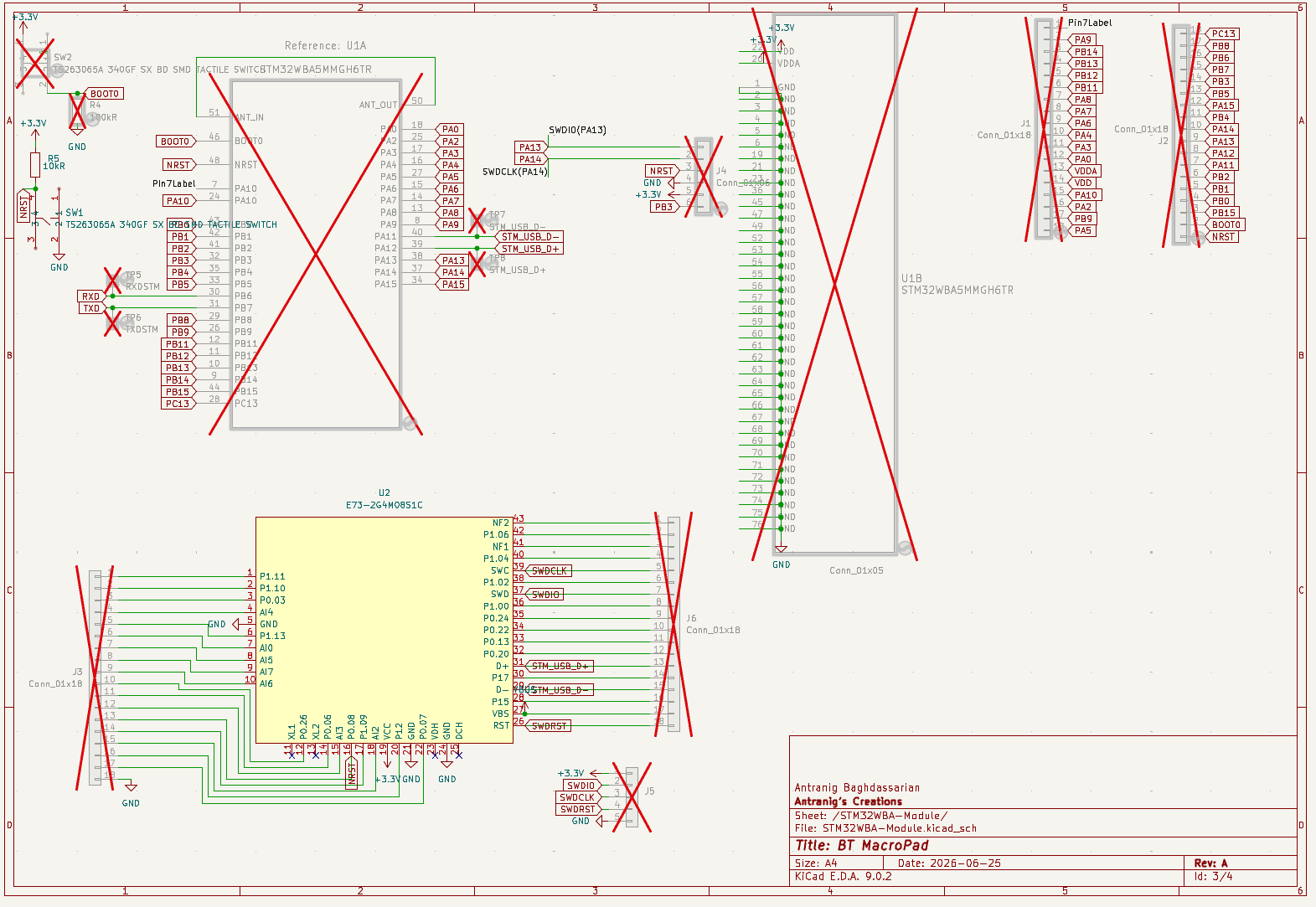
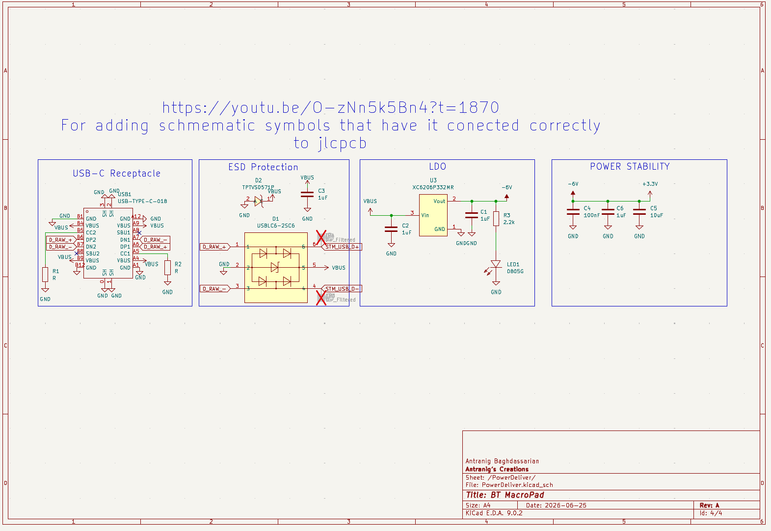
Access the KiCad PCB file here.
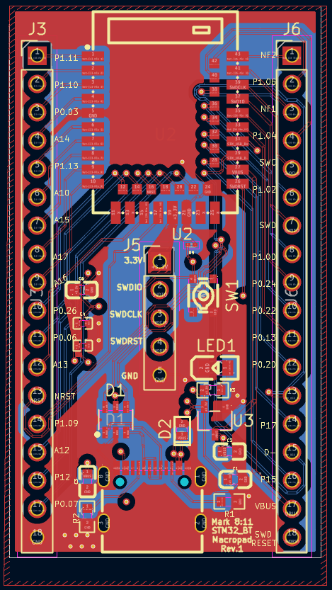
All four copper layers shown together.
| Layer 1: Signal | Layer 2: Ground |
|---|---|
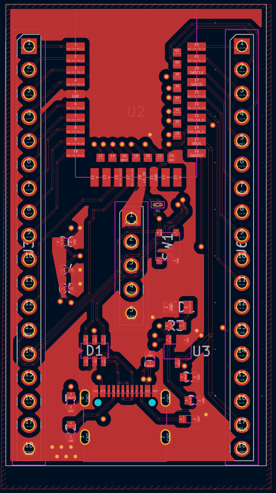 | 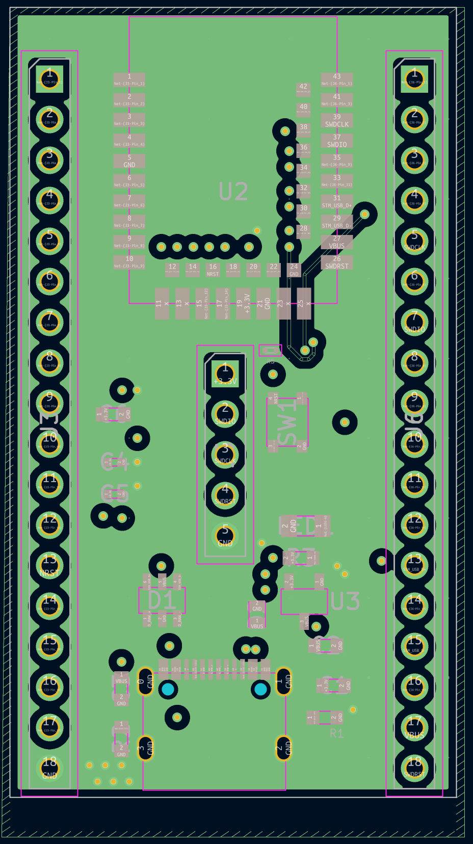 |
| Layer 3: Power | Layer 4: Signal |
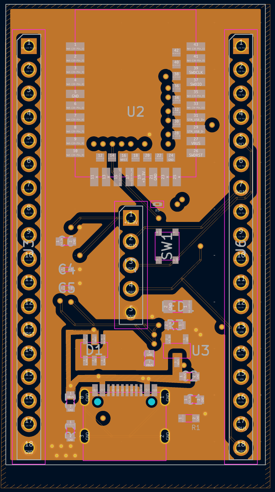 | 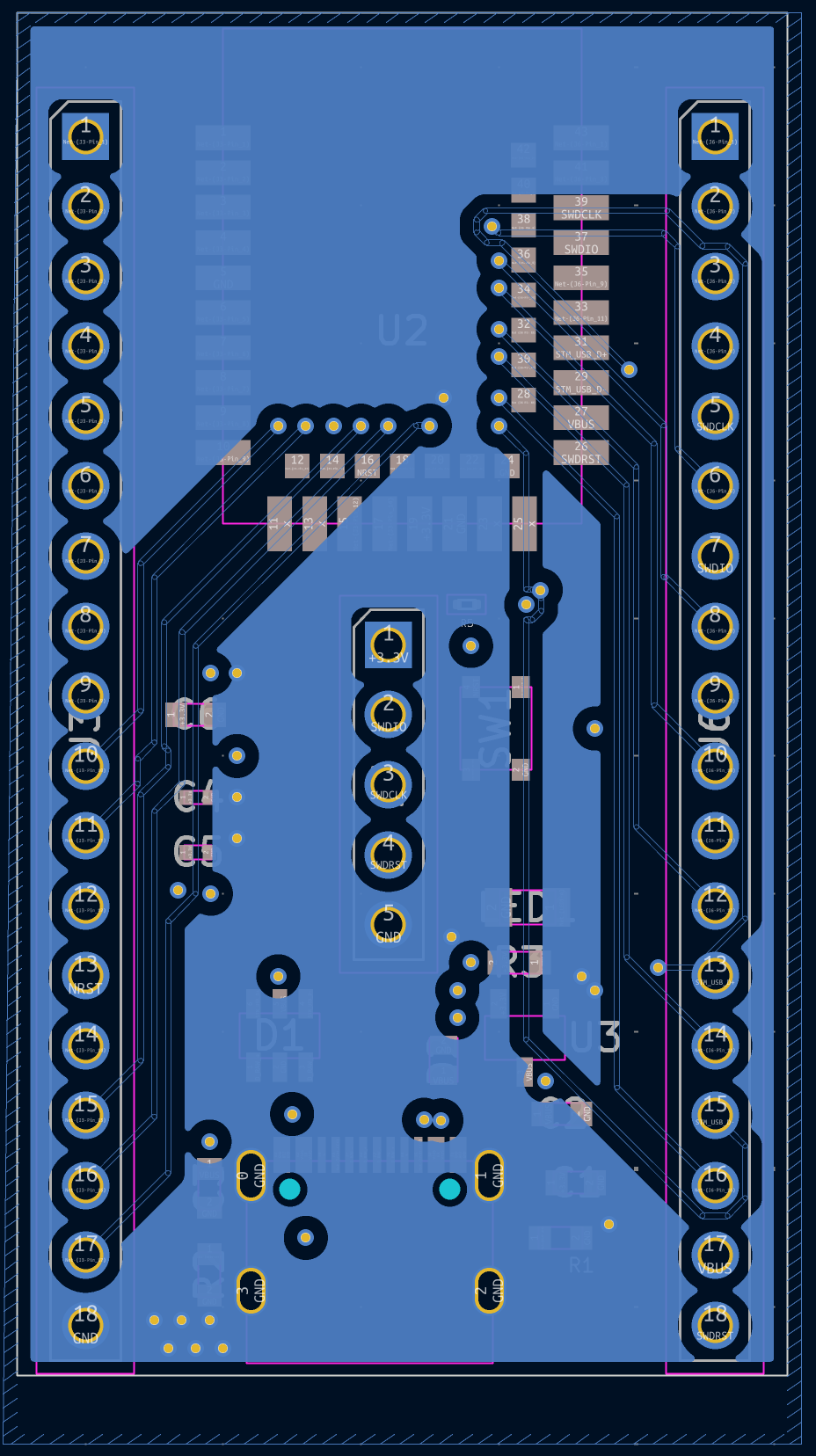 |
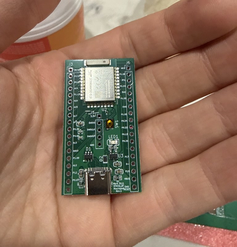
The assembled BT MacroPad PCB, shown in hand for scale.
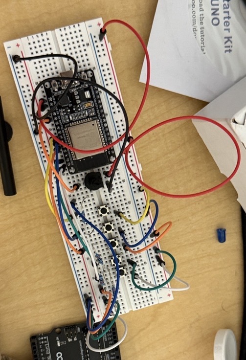
The intial code is for an ESP-32 and written in C++ as an Arduino Sketch (found here as: BLE_Test_Jul28_RunningAverage.ino)
It looked like this:
| Qty | Value | Footprint | References |
|---|---|---|---|
| 5 | 1uF | EasyEDA:C0603 | C1, C2, C3, C6, C8 |
| 2 | 100nF | EasyEDA:C0402 | C4, C7 |
| 2 | Conn_01x18 | Connector_PinHeader_2.54mm:PinHeader_1x18_P2.54mm_Vertical | J1, J2 |
| 2 | R | Resistor_SMD:R_0201_0603Metric | R1, R2 |
| 2 | TS263065A 340GF SX BD SMD TACTILE SWITCH | EasyEDA:SW-SMD_4P-L3.0-W2.6-P1.80-LS3.4-TL | SW1, SW2 |
| 1 | 0805G | EasyEDA:LED0805-R-RD | LED1 |
| 1 | 100kR | Resistor_SMD:R_0201_0603Metric | R4 |
| 1 | 10kR | Resistor_SMD:R_0201_0603Metric | R5 |
| 1 | 10uF | Capacitor_SMD:C_0201_0603Metric | C5 |
| 1 | 2.2k | EasyEDA:R0603 | R3 |
| 1 | CH340C | EasyEDA:SOP-16_L10.0-W3.9-P1.27-LS6.0-BL | U4 |
| 1 | CH340C_RXD | Connector_Pin:Pin_D1.0mm_L10.0mm | TP2 |
| 1 | CH340C_TXD | Connector_Pin:Pin_D1.0mm_L10.0mm | TP1 |
| 1 | Conn_01x06 | Connector_PinHeader_2.54mm:PinHeader_1x06_P2.54mm_Vertical | J4 |
| 1 | D+_Filtered | Connector_Pin:Pin_D1.0mm_L10.0mm | TP4 |
| 1 | D+_SolderJumper | Jumper:SolderJumper-3_P1.3mm_Bridged12_Pad1.0x1.5mm_NumberLabels | JP1 |
| 1 | D-_Filtered | Connector_Pin:Pin_D1.0mm_L10.0mm | TP3 |
| 1 | D-_SolderJumper | Jumper:SolderJumper-3_P1.3mm_Bridged12_Pad1.0x1.5mm_NumberLabels | JP2 |
| 1 | RXDSTM | Connector_Pin:Pin_D1.0mm_L10.0mm | TP5 |
| 1 | STM32WBA5MMGH6TR | STM32WBA5MMGH6TR:SIP-LGA76_STM | U1 |
| 1 | STM_USB_D+ | Connector_Pin:Pin_D1.0mm_L10.0mm | TP8 |
| 1 | STM_USB_D- | Connector_Pin:Pin_D1.0mm_L10.0mm | TP7 |
| 1 | TPTVS0571P | EasyEDA:DFN-2_L1.6-W1.0-P1.10-RD | D2 |
| 1 | TXDSTM | Connector_Pin:Pin_D1.0mm_L10.0mm | TP6 |
| 1 | USB-TYPE-C-018 | EasyEDA:USB-C_SMD-TYPE-C-31-M-12 | USB1 |
| 1 | USBLC6-2SC6 | EasyEDA:SOT-23-6_L2.9-W1.6-P0.95-LS2.8-BL | D1 |
| 1 | XC6206P332MR | EasyEDA:SOT-23-3_L2.9-W1.6-P1.90-LS2.8-BR | U3 |
AntranigB/BT-MacroPad
All of these make it hard to handle keyboard, especially from afar. BUT what if while you're doing those you want to:

AntranigB/BT-MacroPad
All of these make it hard to handle keyboard, especially from afar. BUT what if while you're doing those you want to:

Galacs/esp32s3-poc-devboard
ESP32-S3 based PoC board made to test step-down power supply design, 24v level shifter, crystal circuits and RF circuit

ikuto0815/eink_mahjong_compass
This repo contains all the files neccesary to build a bluetooth controlled digital mahjong compass.


karlp/kcell-faker
fake a load cell, for testing functional behaviour with changing loads.

HeyPCB/whisker
Drop-in controller for Petoi's Nybble robot cat running the stock OpenCat firmware: ATmega328P, PCA9685, MPU-6050, USB-C, 3 A buck, protected battery input. 4-layer KiCad 10 board plus printed cradle.

MarceloSalazar/LPC1114-LCD
Las librerías del proyecto se referencian con ${KIPRJMOD} en sym-lib-table y fp-lib-table, así que el proyecto se abre directamente sin configurar nada.

JohnanLuca02/BYTE_Electronics
Repository for everything concerning the electronics (PCB, Electrical schemes, BOM, ...) of the robot dog project of the AiTeam called BYTE.

robocore-labs/link101-hardware
link101 is a multi-protocol USB interface board. One Type-C cable gives you CAN-FD, RS485, Dynamixel, Feetech, UART, I2C, and MIT Cheetah-protocol ports, all as stable Linux devices.
It measures 26 × 52 mm and has 4 copper layers, 1.6 mm thick.
35 parts, built around the CH340C, XC6206P332MR-G, KT-0805G and TPTVS0571P. The full list of its parts is on this page, with links to each part's symbol and footprint where PCBKit's library has them.
From the AntranigB/BT-MacroPad repository on GitHub, at the commit this page was made from: the board is BT_MacroPad/PCB_BT MacroPad/Previous Named Versions/BT MacroPad _ with STM.kicad_pcb and its schematic BT_MacroPad/PCB_BT MacroPad/BT MacroPad.kicad_sch. PCBKit opens the board in the browser, with nothing to install.
Its repository states no licence, so its author keeps all rights: ask AntranigB before reusing the design.