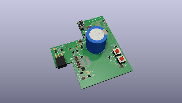
2 layers135.1 × 159.4 mm

 Andreasdahlberg/zkmeter
ZK-meter is a Zigbee HAN-module for Kamstrup Omnipower electricity meters.
Main pcb is an open-source printed circuit board by Andreasdahlberg, from the Andreasdahlberg/zkmeter repository on GitHub, published under the CC0-1.0 licence. It is a 4-layer board of 62 × 67 mm with 57 parts on 55 nets, routed with 295 tracks and 58 vias.
It is built around the LM5165YDRC, ESP32-H2-MINI-1U and 1N4148W, with the 1N5819WS, SP0503BAHTG and SI2323DS among its other parts. Its parts include 16 capacitors, 14 resistors, 4 diodes, 3 switches and 2 ICs. It belongs with the radio and wireless boards and the ESP32 and RISC-V boards of this library.


ZK-meter is a Zigbee HAN-module for Kamstrup Omnipower electricity meters.
Open the HAN-Module casing:
Replace the PCB:
Secure the Top Cover:
Insert the HAN-Module:
Activate Pairing Mode:
| Qty | Value | Footprint | References |
|---|---|---|---|
| 5 | 10k | Resistor_SMD:R_1206_3216Metric_Pad1.30x1.75mm_HandSolder | R1, R5, R6, R7, R8 |
| 4 | 1uF | Capacitor_SMD:C_1206_3216Metric_Pad1.33x1.80mm_HandSolder | C4, C5, C7, C11 |
| 4 | 4.7uF | Capacitor_SMD:C_1206_3216Metric_Pad1.33x1.80mm_HandSolder | C3, C6, C15, C16 |
| 3 | 0 | Resistor_SMD:R_1206_3216Metric_Pad1.30x1.75mm_HandSolder | R10, R11, R12 |
| 2 | 0.1uF | Capacitor_SMD:C_1206_3216Metric_Pad1.33x1.80mm_HandSolder | C1, C12 |
| 2 | 10uF | Capacitor_SMD:C_1206_3216Metric_Pad1.33x1.80mm_HandSolder | C2, C10 |
| 2 | 12pF | Capacitor_SMD:C_1206_3216Metric_Pad1.33x1.80mm_HandSolder | C13, C14 |
| 2 | 5k1 | Resistor_SMD:R_1206_3216Metric_Pad1.30x1.75mm_HandSolder | R3, R4 |
| 2 | SolderJumper_2_Bridged | Jumper:SolderJumper-2_P1.3mm_Open_TrianglePad1.0x1.5mm | JP1, JP3 |
| 1 | +3.3V | TestPoint:TestPoint_THTPad_D2.0mm_Drill1.0mm | TP3 |
| 1 | 1.1 | Resistor_SMD:R_1206_3216Metric_Pad1.30x1.75mm_HandSolder | R14 |
| 1 | 110k | Resistor_SMD:R_1206_3216Metric_Pad1.30x1.75mm_HandSolder | R2 |
| 1 | 1F | Capacitor_THT:CP_Radial_D18.0mm_P7.50mm | C8 |
| 1 | 1N4148W | Diode_SMD:D_SOD-123 | D4 |
| 1 | 1N5819WS | Diode_SMD:D_SOD-323 | D3 |
| 1 | 32.768KHz | Crystal:Crystal_SMD_Abracon_ABS25-4Pin_8.0x3.8mm | Y1 |
| 1 | 5.1M | Resistor_SMD:R_1206_3216Metric_Pad1.30x1.75mm_HandSolder | R9 |
| 1 | 56uH | Inductor_SMD:L_Wuerth_WE-PD2-Typ-L | L1 |
| 1 | 59k | Resistor_SMD:R_1206_3216Metric_Pad1.30x1.75mm_HandSolder | R13 |
| 1 | 82nF | Capacitor_SMD:C_1206_3216Metric_Pad1.33x1.80mm_HandSolder | C9 |
| 1 | Boot | Button_Switch_SMD:SW_SPST_PTS645 | SW3 |
| 1 | Conn_01x06_Socket | Connector_PinSocket_2.54mm:PinSocket_2x03_P2.54mm_Horizontal | J1 |
| 1 | DATA_IN | TestPoint:TestPoint_THTPad_D1.5mm_Drill0.7mm | TP8 |
| 1 | EN | TestPoint:TestPoint_THTPad_D1.5mm_Drill0.7mm | TP5 |
| 1 | ESP32-H2-MINI-1 | PCM_Espressif:ESP32-H2-MINI-1 | U1 |
| 1 | GND | TestPoint:TestPoint_THTPad_D2.0mm_Drill1.0mm | TP10 |
| 1 | LM5165Y | Package_SO:VSSOP-10_3x3mm_P0.5mm | U2 |
| 1 | PGOOD | TestPoint:TestPoint_THTPad_D1.5mm_Drill0.7mm | TP4 |
| 1 | Pair | Button_Switch_THT:SW_Tactile_SPST_Angled_PTS645Vx31-2LFS | SW1 |
| 1 | RXD | TestPoint:TestPoint_THTPad_D1.5mm_Drill0.7mm | TP6 |
| 1 | Reset | Button_Switch_SMD:SW_SPST_PTS645 | SW2 |
| 1 | SP0503BAHT | Package_TO_SOT_SMD:SOT-143 | D2 |
| 1 | Si2323DS | Package_TO_SOT_SMD:SOT-23 | Q1 |
| 1 | SolderJumper_2_Open | Jumper:SolderJumper-2_P1.3mm_Open_TrianglePad1.0x1.5mm | JP4 |
| 1 | TXD | TestPoint:TestPoint_THTPad_D1.5mm_Drill0.7mm | TP7 |
| 1 | USB_C_Receptacle_USB2.0 | Connector_USB:USB_C_Receptacle_HRO_TYPE-C-31-M-12 | J4 |
| 1 | VBUS | TestPoint:TestPoint_THTPad_D1.5mm_Drill0.7mm | TP9 |
| 1 | VDD | TestPoint:TestPoint_THTPad_D2.0mm_Drill1.0mm | TP2 |
| 1 | VIN | TestPoint:TestPoint_THTPad_D1.5mm_Drill0.7mm | TP1 |
| 1 | WS2812B | LED_SMD:LED_WS2812B_PLCC4_5.0x5.0mm_P3.2mm | D1 |

OklahomaOpenSourceHardware/OKC-OSH-2024-Badge
2024 badge for Oklahoma PCB Tech Conferences

fossasia/pslab-hardware
PSLab Hardware Design and Schematics https://pslab.io

StuckAtPrototype/Racer
These are structured into their own files. I could have used submodules, but decided against it.

StuckAtPrototype/AirCube
Works standalone out of the box. Pairs with Home Assistant in minutes. Other platforms are supported through community-contributed extensions.


StuckAtPrototype/PCB_business_card_remake
A custom PCB based "business" card that lets you play a version of Flappy Bird.

It measures 62 × 67 mm and has 4 copper layers, 1.6 mm thick.
57 parts, built around the LM5165YDRC, ESP32-H2-MINI-1U, 1N4148W and 1N5819WS. The full list of its parts is on this page, with links to each part's symbol and footprint where PCBKit's library has them.
From the Andreasdahlberg/zkmeter repository on GitHub, at the commit this page was made from: the board is pcb/main_pcb.kicad_pcb and its schematic pcb/main_pcb.kicad_sch. PCBKit opens the board in the browser, with nothing to install.
Its repository publishes it under the CC0-1.0 licence: you may reuse it on that licence's terms (keep the author's notice, and for a copyleft licence share your changes alike).