
2 layers116 × 116 mm

 Altairu/ALTAIR_MD_V8
ALTAIR_MD_V8
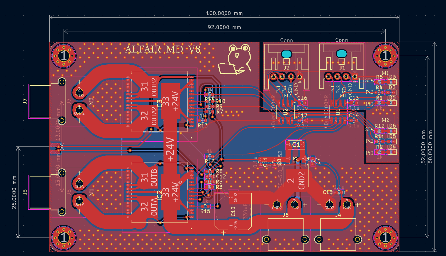
ALTAIR MD V8 is an open-source printed circuit board by Altairu, from the Altairu/ALTAIR_MD_V8 repository on GitHub. It is a 2-layer board of 100 × 60 mm with 49 parts on 38 nets, routed with 706 tracks and 406 vias.
It is built around the ADUM1200AR. Its parts include 16 resistors, 10 capacitors, 6 ICs, 6 diodes and 6 connectors.
High-Power Isolated Motor Driver Board
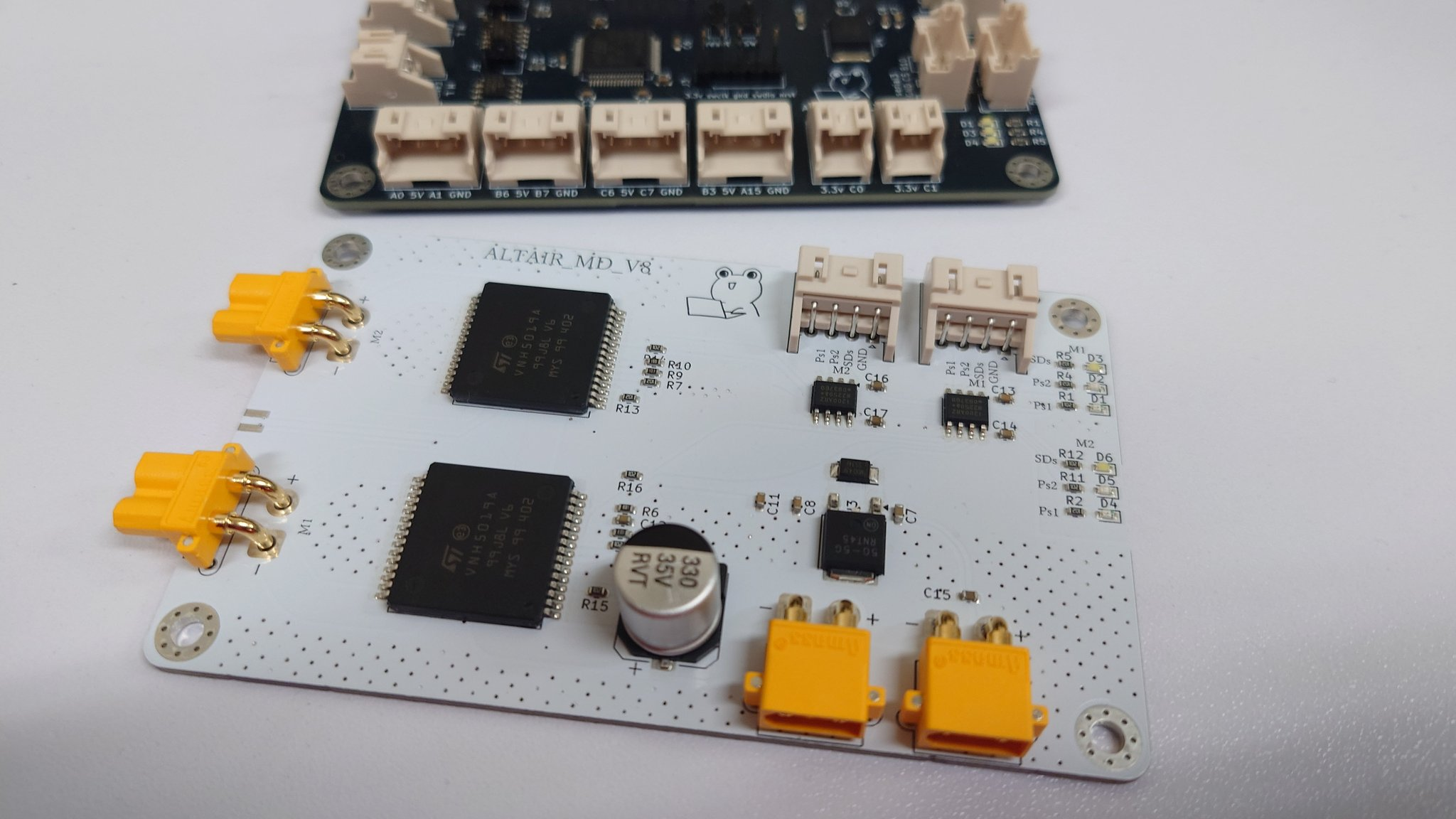
NEWもたどら pic.twitter.com/xIfIAs8RRS
— -Altair- (@Flying___eagle) January 29, 2026
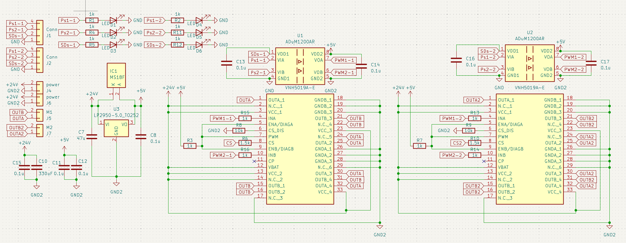
ALTAIR_MD_V8 は、STMicroelectronics製の車載用高出力フルブリッジドライバー VNH5019A-E を搭載したDCモータードライバーモジュールです。
制御信号ラインにデジタルアイソレータ (ADuM121N) を採用することで、モーター駆動系(24V系)とマイコン制御系(3.3V/5V系)のGNDを完全に分離(絶縁)しています。
| 項目 | 仕様 | 備考 |
|---|---|---|
| メインドライバー | STMicroelectronics VNH5019A-E | AEC-Q100準拠 (車載グレード) |
| 絶縁素子 | Analog Devices ADuM121N | 2ch デジタルアイソレータ (計2個使用) |
| 入力電源電圧 | DC 5.5V ~ 24V | パワー側電源 (VCC/VBAT) |
| ロジック入力電圧 | DC 1.8V ~ 5.5V | マイコン側I/O電圧 |
| 最大出力電流 | 連続 12A / ピーク 30A | 放熱条件に依存 |
| 電流センシング | アナログ電圧出力 | 1.5kΩ抵抗接続時 (約0.14V/A) |
| ピン名 | 機能 | 説明 |
|---|---|---|
| PWM1 | INA 入力 | モーター回転方向制御 A (正転/逆転) |
| PWM2 | INB 入力 | モーター回転方向制御 B (正転/逆転) |
| SD | 動作許可 (PWM Pin) | HIGH: 動作許可, LOW: フリーラン停止 (全OFF) |
| GND | ロジックGND | マイコン側のGNDと接続 |
| ピン名 | 機能 | 説明 |
|---|---|---|
| +24V | 電源入力 (+) | モーター用メイン電源 (最大24V) |
| GND_P | パワーGND (-) | 電源およびモーターのグラウンド |
| OUT A | モーター出力 A | モーターの端子へ接続 |
| OUT B | モーター出力 B | モーターの端子へ接続 |
| CS | 電流センス出力 | 電流値に応じたアナログ電圧を出力 (ADCで読取可) |
VNH5019A-E の仕様に基づく真理値表です。 SD (Shutdown/Enable) ピンが HIGH の時のみモーターが駆動します。
| SD (Enable) | PWM1 (INA) | PWM2 (INB) | OUT A | OUT B | 動作モード |
|---|---|---|---|---|---|
| L | X | X | OPEN | OPEN | フリーラン停止 (All OFF) |
| H | H | L | H | L | 正転 (CW) |
| H | L | H | L | H | 逆転 (CCW) |
| H | L | L | L | L | ブレーキ (GNDショート) |
| H | H | H | H | H | ブレーキ (VCCショート) |
CSピンからは、モーター電流に比例した電流が出力されます。基板上の 1.5kΩ 抵抗により電圧に変換されています。
| Qty | Value | Footprint | References |
|---|---|---|---|
| 12 | 1k | Resistor_SMD:R_0603_1608Metric | R1, R2, R3, R4, R5, R7, R11, R12, R13, R14, R15, R16 |
| 8 | 0.1u | Capacitor_SMD:C_0603_1608Metric | C8, C11, C12, C13, C14, C15, C16, C17 |
| 6 | LED | LED_SMD:LED_0603_1608Metric | D1, D2, D3, D4, D5, D6 |
| 4 | MountingHole | MountingHole:MountingHole_3.2mm_M3_Pad_Via | H1, H2, H3, H4 |
| 2 | 1.5k | Resistor_SMD:R_0603_1608Metric | R6, R10 |
| 2 | 10k | Resistor_SMD:R_0603_1608Metric | R8, R9 |
| 2 | ADuM1200AR | Package_SO:SOIC-8_3.9x4.9mm_P1.27mm | U1, U2 |
| 2 | Conn | Connector_JST:JST_XA_S04B-XASK-1_1x04_P2.50mm_Horizontal | J1, J2 |
| 2 | VNH5019A-E | KiCad:VNH5019AE | IC2, IC3 |
| 2 | power | Connector_AMASS:AMASS_XT30PW-M_1x02_P2.50mm_Horizontal | J4, J6 |
| 1 | 330uF | Capacitor_SMD:CP_Elec_10x10 | C10 |
| 1 | 47u | Capacitor_SMD:C_0603_1608Metric | C7 |
| 1 | LOGO | LOGO | G*** |
| 1 | LP2950-5.0_TO252 | Package_TO_SOT_SMD:TO-252-2 | U3 |
| 1 | M1 | Connector_AMASS:AMASS_XT30PW-F_1x02_P2.50mm_Horizontal | J5 |
| 1 | M2 | Connector_AMASS:AMASS_XT30PW-F_1x02_P2.50mm_Horizontal | J7 |
| 1 | MS18F | KiCad:SODFL4725X110N | IC1 |


It measures 100 × 60 mm and has 2 copper layers, 1.6 mm thick.
49 parts, built around the ADUM1200AR. The full list of its parts is on this page, with links to each part's symbol and footprint where PCBKit's library has them.
From the Altairu/ALTAIR_MD_V8 repository on GitHub, at the commit this page was made from: the board is AltairMD_V8.kicad_pcb and its schematic AltairMD_V8.kicad_sch. PCBKit opens the board in the browser, with nothing to install.
Its repository states no licence, so its author keeps all rights: ask Altairu before reusing the design.