
2 layers187.2 × 26.6 mm

This Project is my shot at this. I use custom hardware (build on perf-board) to archive this goal. I have build a 2-Channel 16bit DAC with an refresh rate of around 1 MSample per second.
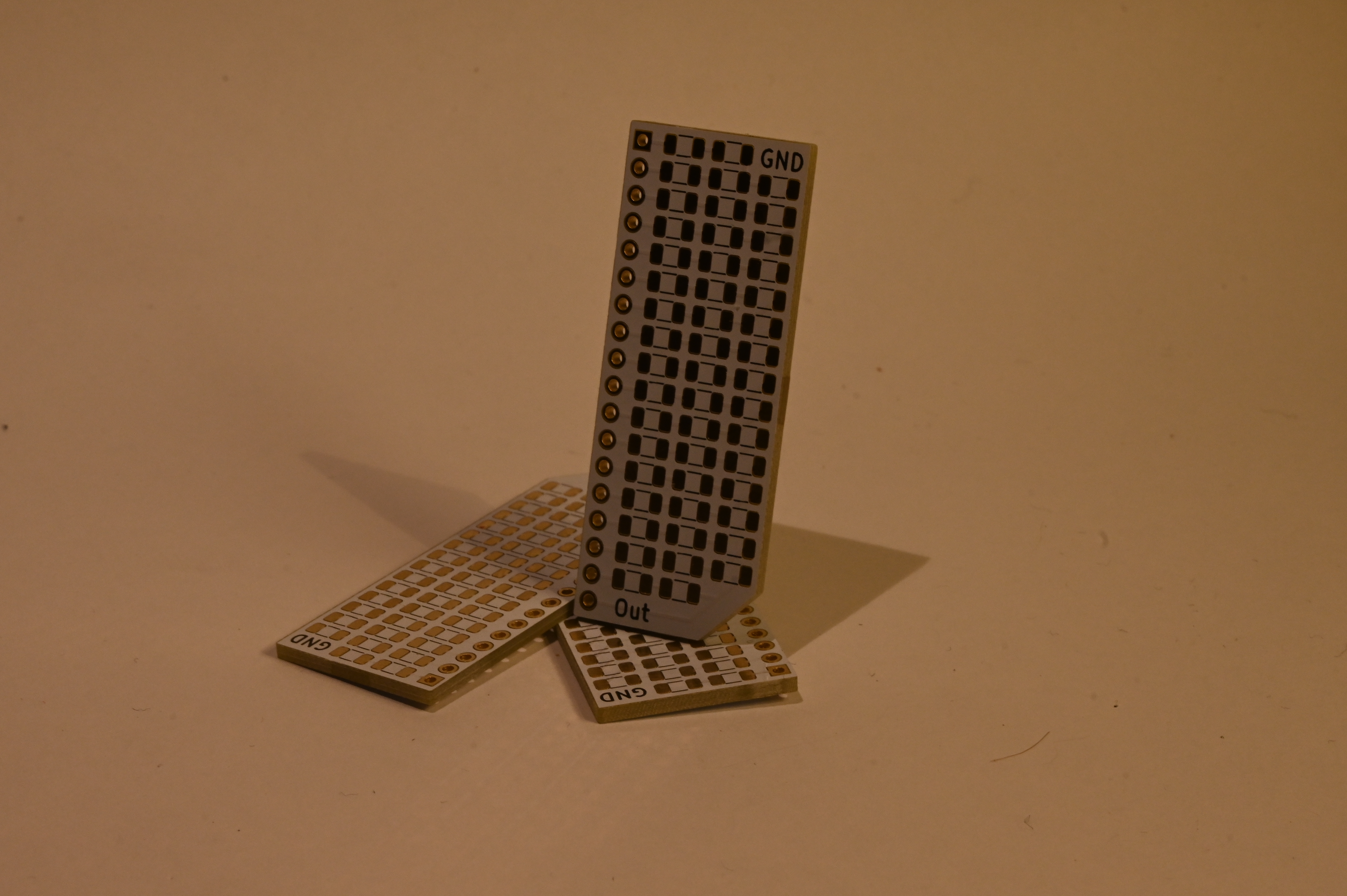
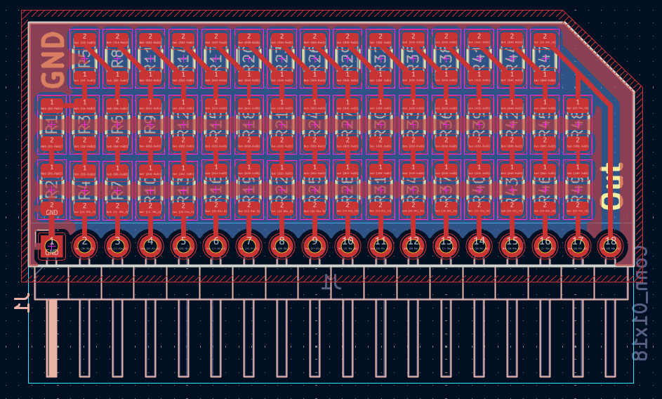
Dac pcb is an open-source printed circuit board by AlexanderHD27, from the AlexanderHD27/oscilloscope-drawing repository on GitHub, published under the MIT licence. It is a 2-layer board of 46.7 × 18.8 mm with 50 parts on 50 nets, routed with 84 tracks and 0 vias.
Its parts include 49 resistors and 1 connector. It belongs with the audio and music boards of this library.
A device that draws on an oscilloscope.
Drawing on analog oscilloscope is almost a classic in the electronics/microcontroller community now. This is done by setting the scope to XY-Mode and then controlling the X/Y-deflection of the electron-beam. My Scope has no Z-Channel. I cannot control the intensity of beam (or switches off) by voltage yet
This Project is my shot at this. I use custom hardware (build on perf-board) to archive this goal. I have build a 2-Channel 16bit DAC with an refresh rate of around 1 MSample per second. Further more a usb-interface + driver shall be developed.
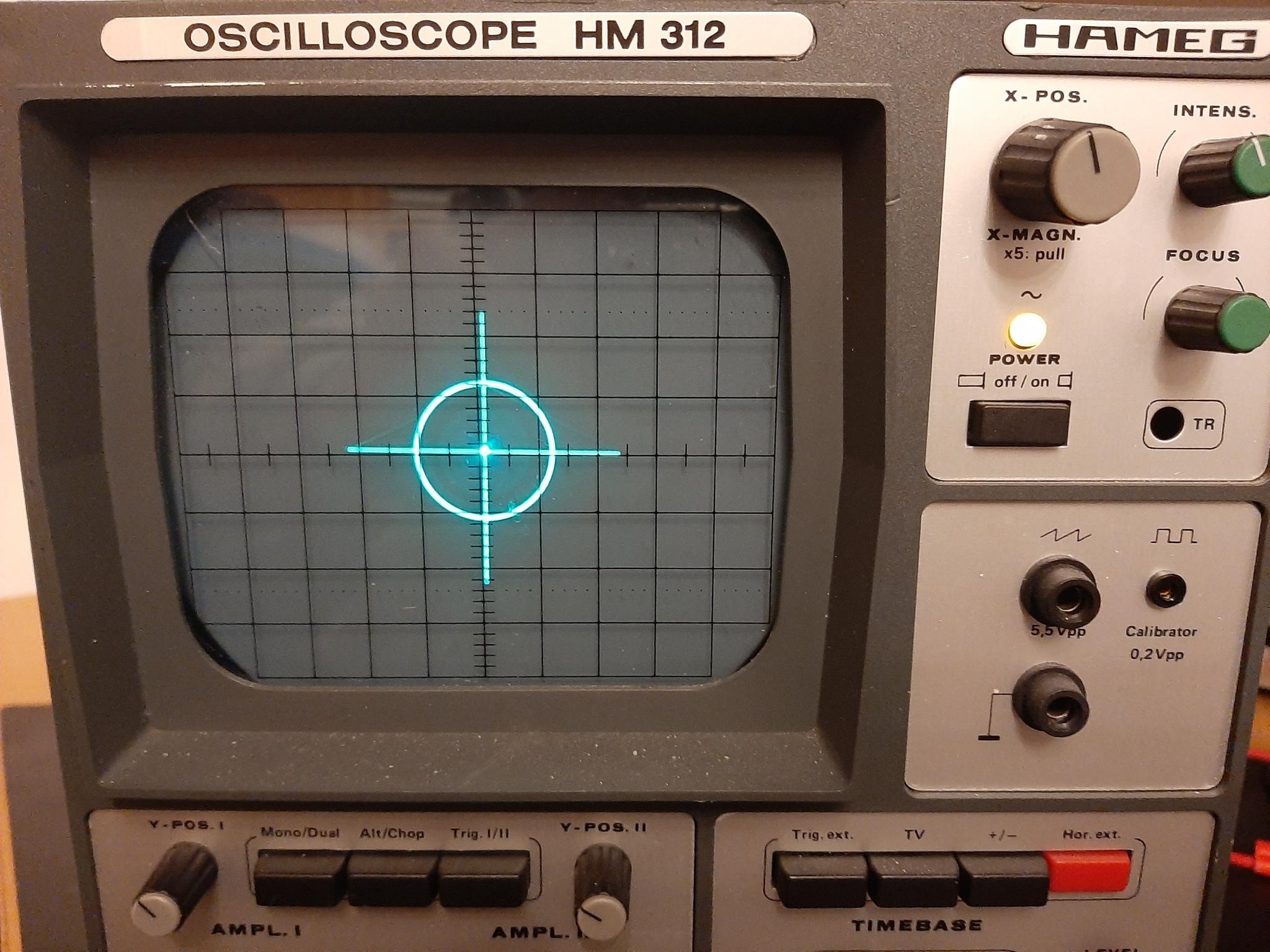
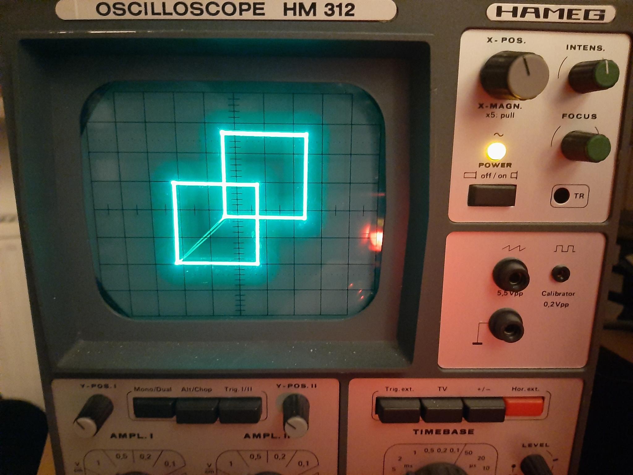
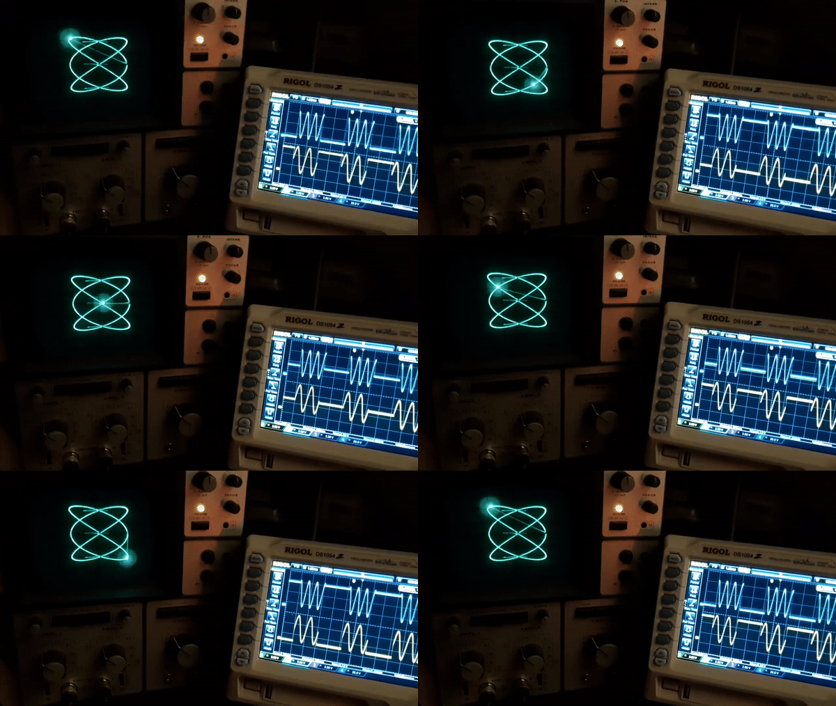
My current todo list can be found here
Everything is solder onto pref-boards an connected via pin-headers and jumpers
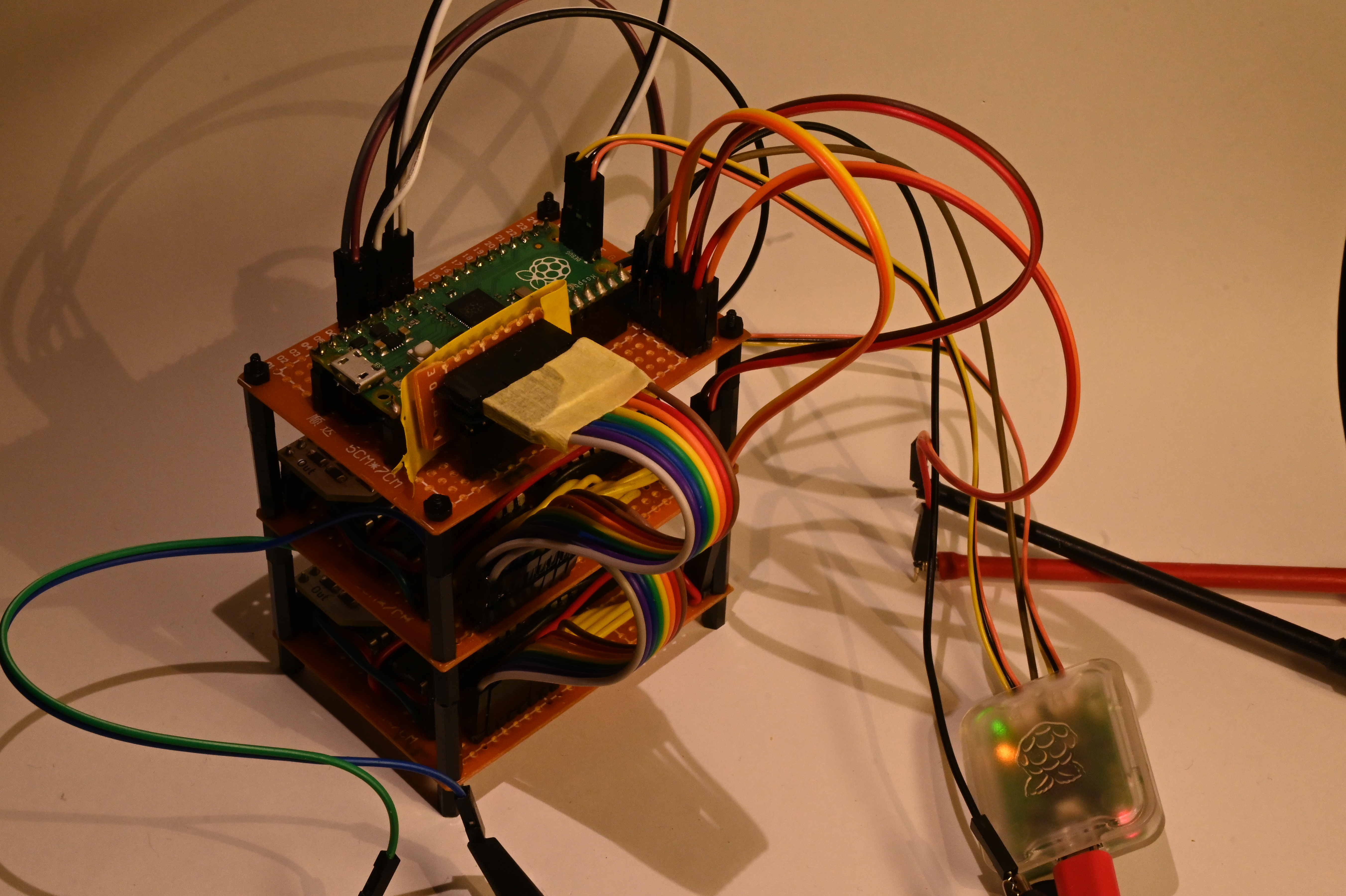

(Diagram of the System-Hardware components)
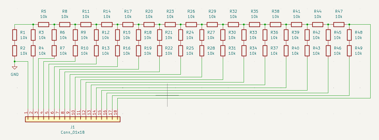
The DACs are R-2R-Ladder DAC on a made custom PCB. The Input-Bits are feed from Octal-D-Latches (74HC573) in combination with some other logic ICs to reduce pin usage on the RPi Pico. Data sent via a 8-bit a parallel Bus to
At 1 MHz Square Wave, the analog output signal quality is significantly degraded. Testing revealed that probably R-2R_Ladder DAC is the weak link and needs further improvement. I currently use R = 11kOhm.
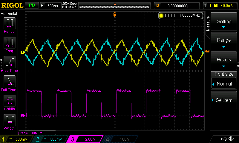
Yellow: X-Channel, Blue: Y-Channel, Magenta: Digital Input Signal to the DAC. (Yellow and Blue are coupled to AC, they usually to remove the 2.5V offset)
For testing the optics I did use a Hameg MH 312 Oscilloscope (I got this one used from Kleinanzeigen, so its already falling apart: semi-broken Coupling-switch, not being able focus the beam correctly, X-Pos nob falling off all the time)
| Qty | Value | Footprint | References |
|---|---|---|---|
| 49 | 10k | Resistor_SMD:R_1206_3216Metric | R1, R2, R10, R11, R12, R13, R14, R15, R16, R17, R18, R19, R20, R21, R22, R23 +33 |
| 1 | Conn_01x18 | Connector_PinHeader_2.54mm:PinHeader_1x18_P2.54mm_Horizontal | J1 |


hackclub/OnBoard
💡 Join 1,000 teenagers and make your first PCB with a $100 grant!

dmcke5/NucDeck
The Open Source DIY Handheld Gaming PC!


roarfred/AmsToMqttBridge
Minimalistic system to read AMS/HAN data from electrical meter
It measures 46.7 × 18.8 mm and has 2 copper layers, 1.6 mm thick.
50 parts. The full list of its parts is on this page, with links to each part's symbol and footprint where PCBKit's library has them.
From the AlexanderHD27/oscilloscope-drawing repository on GitHub, at the commit this page was made from: the board is circuits/dac-pcb/dac-pcb.kicad_pcb and its schematic circuits/dac-pcb/dac-pcb.kicad_sch. PCBKit opens the board in the browser, with nothing to install.
Its repository publishes it under the MIT licence: you may reuse it on that licence's terms (keep the author's notice, and for a copyleft licence share your changes alike).