



2 layers74 × 41 mm
MBus USB 12
greenMikeEU/shrdzm
SHRDZM (just a name, not an acronym) is an ESP8285/ESP8266 based sensor and actor integration platform.
29 partsGPL-3.0

 roarfred/AmsToMqttBridge223
Minimalistic system to read AMS/HAN data from electrical meter
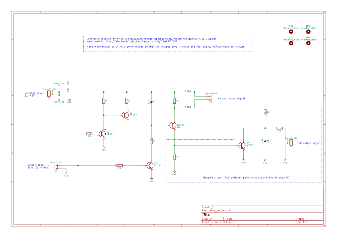
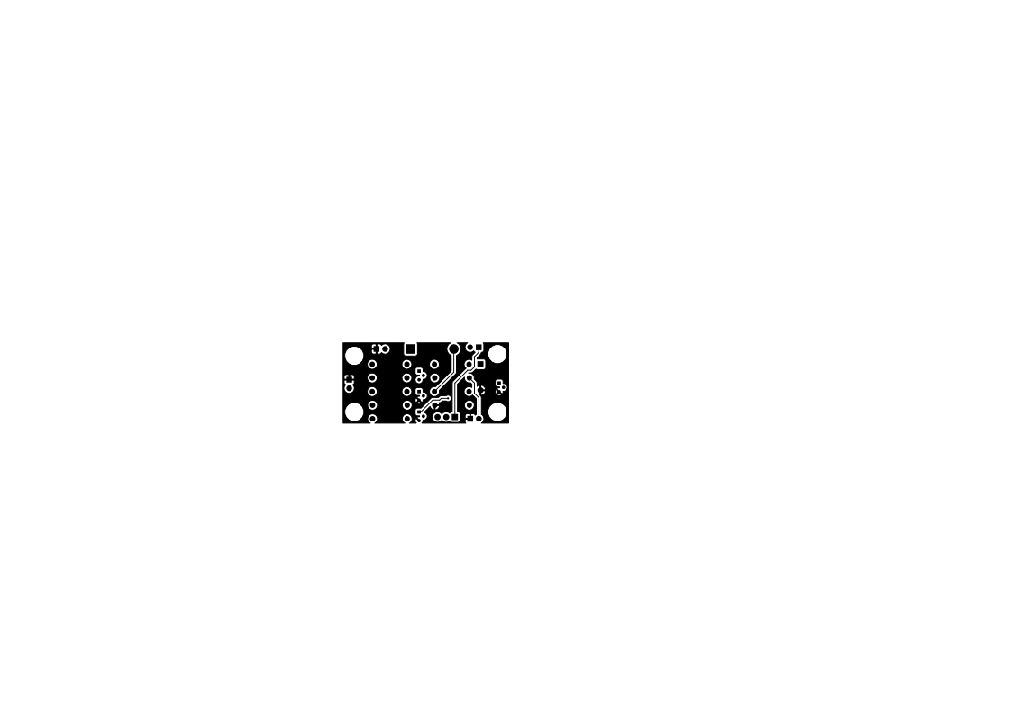
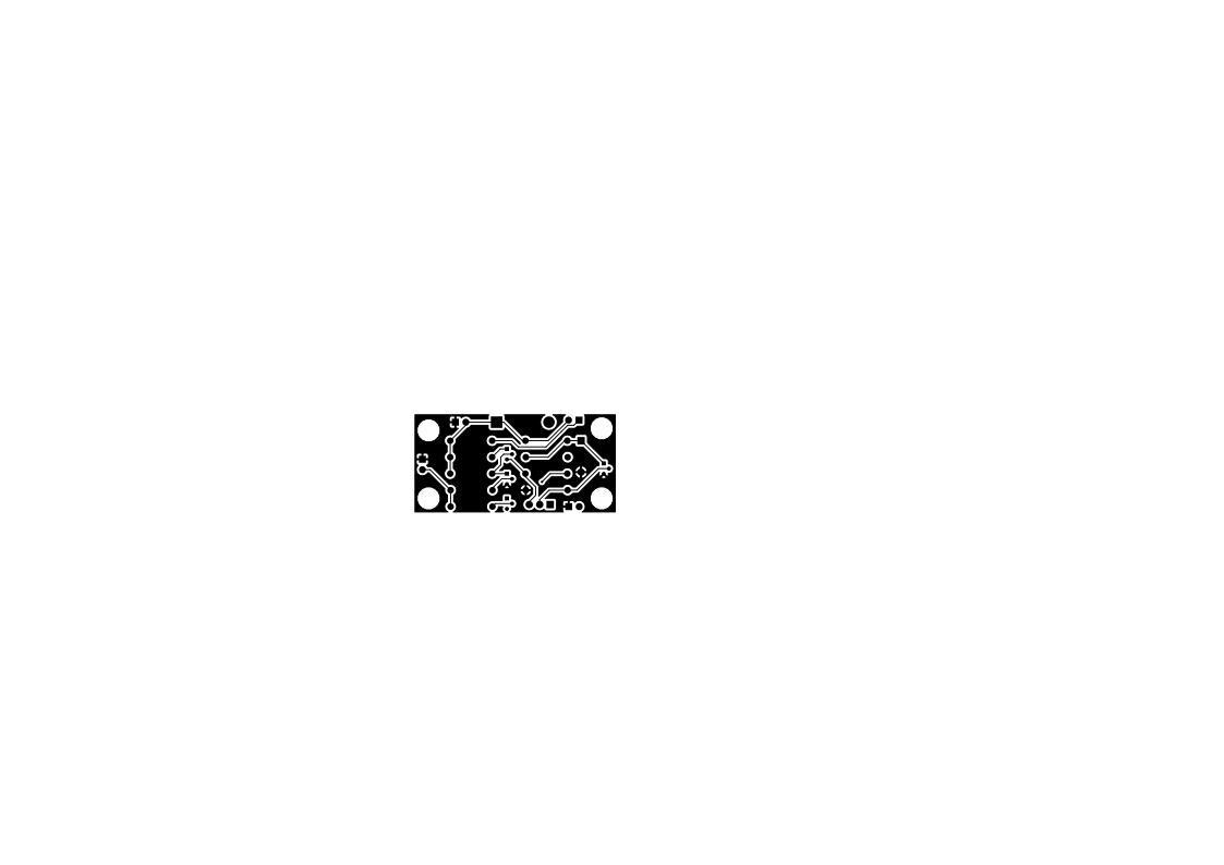
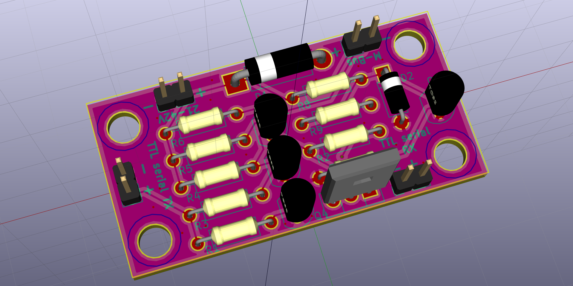
Mbus master is an open-source printed circuit board by roarfred, from the roarfred/AmsToMqttBridge repository on GitHub. It is a 2-layer board of 50 × 25 mm with 50 parts on 13 nets, routed with 72 tracks and 1 via.
It is built around the BC337 and BD136. Its parts include 9 resistors, 5 transistors, 4 connectors and 2 diodes. It belongs with the home automation and IoT boards and the ESP8266 boards of this library.
This board can be used to simulate a M-Bus master device instead of connecting to the real AMS unit, i.e. usable for test and development. It takes a 5 V TTL level input (serial) signal and converts it to a M-bus level signal. It supports both sending and receiving. Inspired by MBus_USB.pdf1, although significantly improved by using zener diodes so that it is flexible and can work with any external power source between 21 and 42 Volt. Most DC-DC boost/step-up converter modules2 should be fine for this.
Note for the 13V zener. This board design depends on the zener to operate below 1mA, e.g. like 1N5350 (figure 8) whereas a BZX55 (figure 9) will maybe not operate properly.
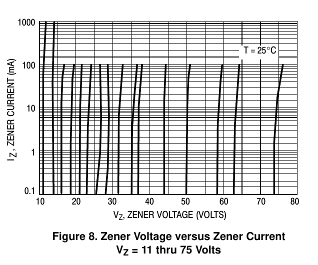
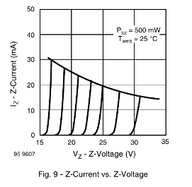
This limitation could be lifted by reducing the 8.2k resistor so that it draws enough current.
Rev A - Only transmit. Wrong design, does not work. Rev B - Both transmit and receive. Should work (not tested yet).
1 See also https://electronics.stackexchange.com/questions/99388/designing-a-m-bus-master-up-to-10-slaves/ and https://electronics.stackexchange.com/a/214477/568.
2 Like for instance this one for £3.
| Qty | Value | Footprint | References |
|---|---|---|---|
| 5 | 10k | Resistors_THT:R_Axial_DIN0207_L6.3mm_D2.5mm_P10.16mm_Horizontal | R1, R3, R4, R5, R8 |
| 4 | BC337 | TO_SOT_Packages_THT:TO-92_Molded_Narrow | Q1, Q2, Q3, Q5 |
| 4 | Conn_01x02 | Pin_Headers:Pin_Header_Straight_1x02_Pitch2.54mm | J1, J2, J3, J4 |
| 4 | Mounting_Hole | Mounting_Holes:MountingHole_4.3mm_M4_ISO14580 | MK1, MK2, MK3, MK4 |
| 1 | 13V | Diodes_THT:D_5W_P12.70mm_Horizontal | D1 |
| 1 | 1k | Resistors_THT:R_Axial_DIN0207_L6.3mm_D2.5mm_P10.16mm_Horizontal | R9 |
| 1 | 220k | Resistors_THT:R_Axial_DIN0207_L6.3mm_D2.5mm_P10.16mm_Horizontal | R6 |
| 1 | 4.7V | Diodes_THT:D_A-405_P7.62mm_Horizontal | D2 |
| 1 | 8.2k | Resistors_THT:R_Axial_DIN0207_L6.3mm_D2.5mm_P10.16mm_Horizontal | R2 |
| 1 | 82 | Resistors_THT:R_Axial_DIN0207_L6.3mm_D2.5mm_P10.16mm_Horizontal | R7 |
| 1 | BD136 | TO_SOT_Packages_THT:TO-126_Vertical | Q4 |
| 1 | LOGO | LOGO | G*** |
The 25 most common of 50 parts.
greenMikeEU/shrdzm
SHRDZM (just a name, not an acronym) is an ESP8285/ESP8266 based sensor and actor integration platform.

AlexLymbo/Folder-Trimmer
Folder Trimmer 🗂️✨ A simple script to clean up unnecessary files from your projects (currently only for KiCad projects)

arafat-siju/electronics-projects
A hardware-based fastest finger quiz system using digital logic ICs, featuring timer control, first-response detection, input lockout, and timeout indication.


It measures 50 × 25 mm and has 2 copper layers, 1.6 mm thick.
50 parts, built around the BC337 and BD136. The full list of its parts is on this page, with links to each part's symbol and footprint where PCBKit's library has them.
From the roarfred/AmsToMqttBridge repository on GitHub, at the commit this page was made from: the board is Electrical/MBus_Simulator/mbus_master.kicad_pcb. PCBKit opens the board in the browser, with nothing to install.
Its repository states no licence, so its author keeps all rights: ask roarfred before reusing the design.