4 layers50 × 74 mm
Compute Node
AkshathRaghav/boilernet
Code release for BoilerNet, demo'd at SPARK S'25 as a Purdue Senior Design Capstone. Associated PCB Design and 3D Prints within.
34 parts3Apache-2.0

 AkshathRaghav/boilernet3
Code release for BoilerNet, demo'd at SPARK S'25 as a Purdue Senior Design Capstone. Associated PCB Design and 3D Prints within.
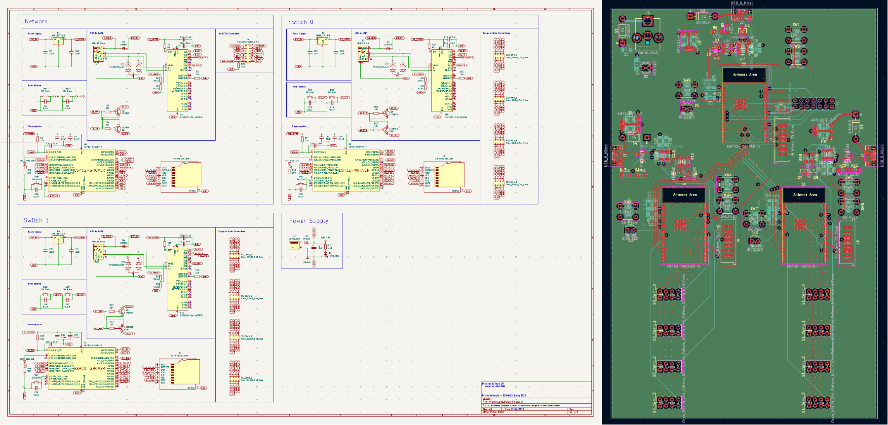
Network and Switch is an open-source printed circuit board by AkshathRaghav, from the AkshathRaghav/boilernet repository on GitHub, published under the Apache-2.0 licence. It is a 4-layer board of 111 × 171 mm with 108 parts on 161 nets, routed with 1,477 tracks and 1,366 vias.
It is built around the ESP32-WROVER-E(4MB), AMS1117-3.3 and PESD5V0L2BT, with the SS8050 among its other parts. Its parts include 31 capacitors, 26 resistors, 19 switches, 10 ICs and 8 diodes. It belongs with the computers and single-board computers boards and the ESP32 boards of this library.




This project aimed to develop a Network Attached Storage utilizing ESP32 MCUs. The aptly-named BoilerNet aims to enable In-Network-compute alongside swappable disks and compute workloads, neatly brought together by a cloud-hosted Dashboard interface. There are a few core ideas that form the foundation for this ”cluster” – Low Power Usage, Plug-and-Play Workloads, High Scalability.
Our reports/presentations are linked in the /docs. They contain in-depth views, reasonings and explanations regarding the design and its motivation. We also outline how we tested and ensured functionality. This repository is just meant to help anyone who wishes to "refer" to our code/designs for their own use-case.
Watch the Demo that won us the "Senior Design Award" for Spring '25 through Purdue ECE: Link!
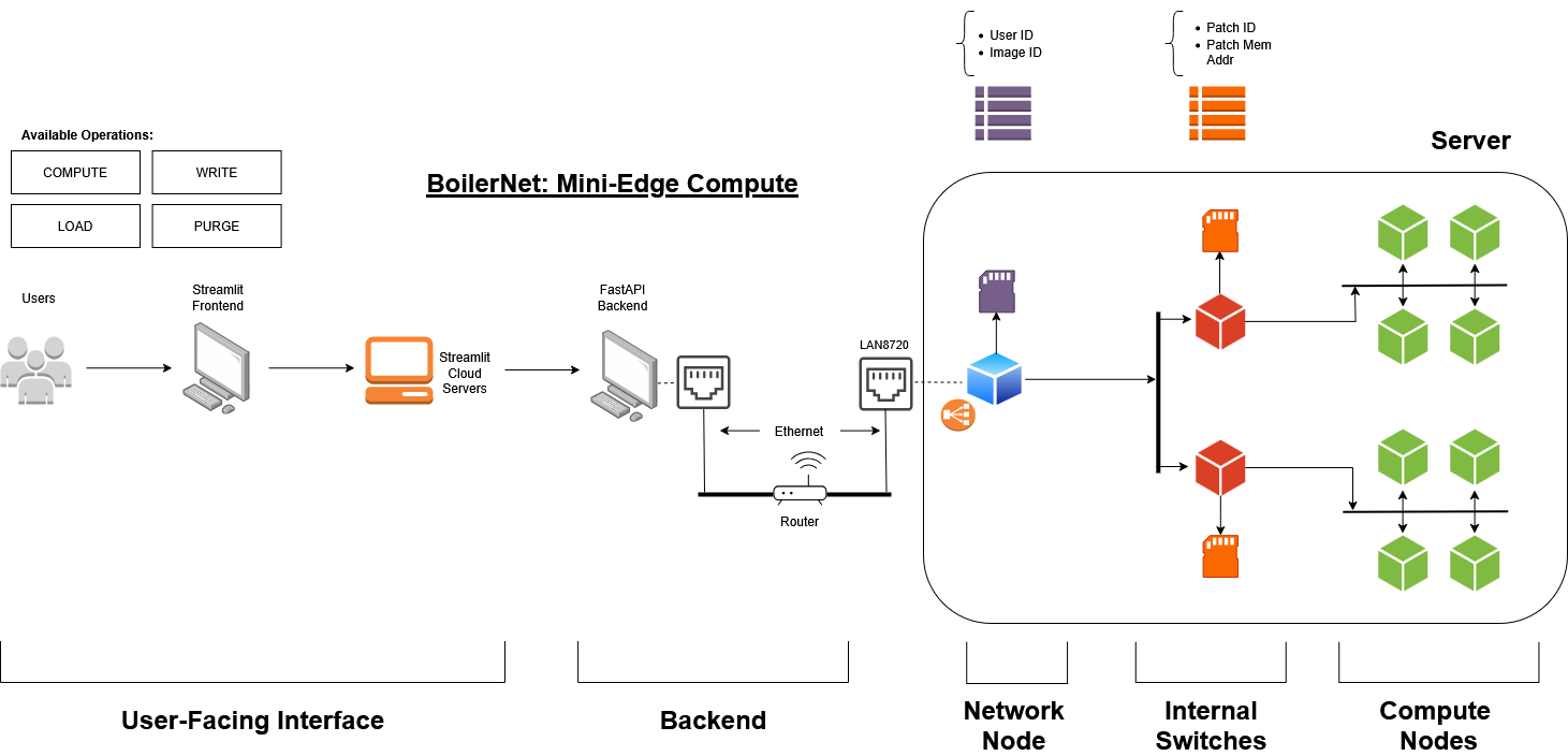
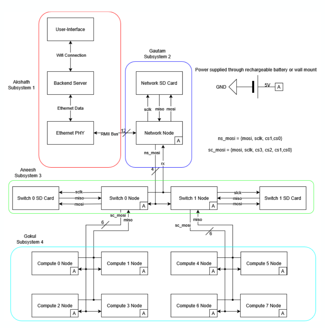
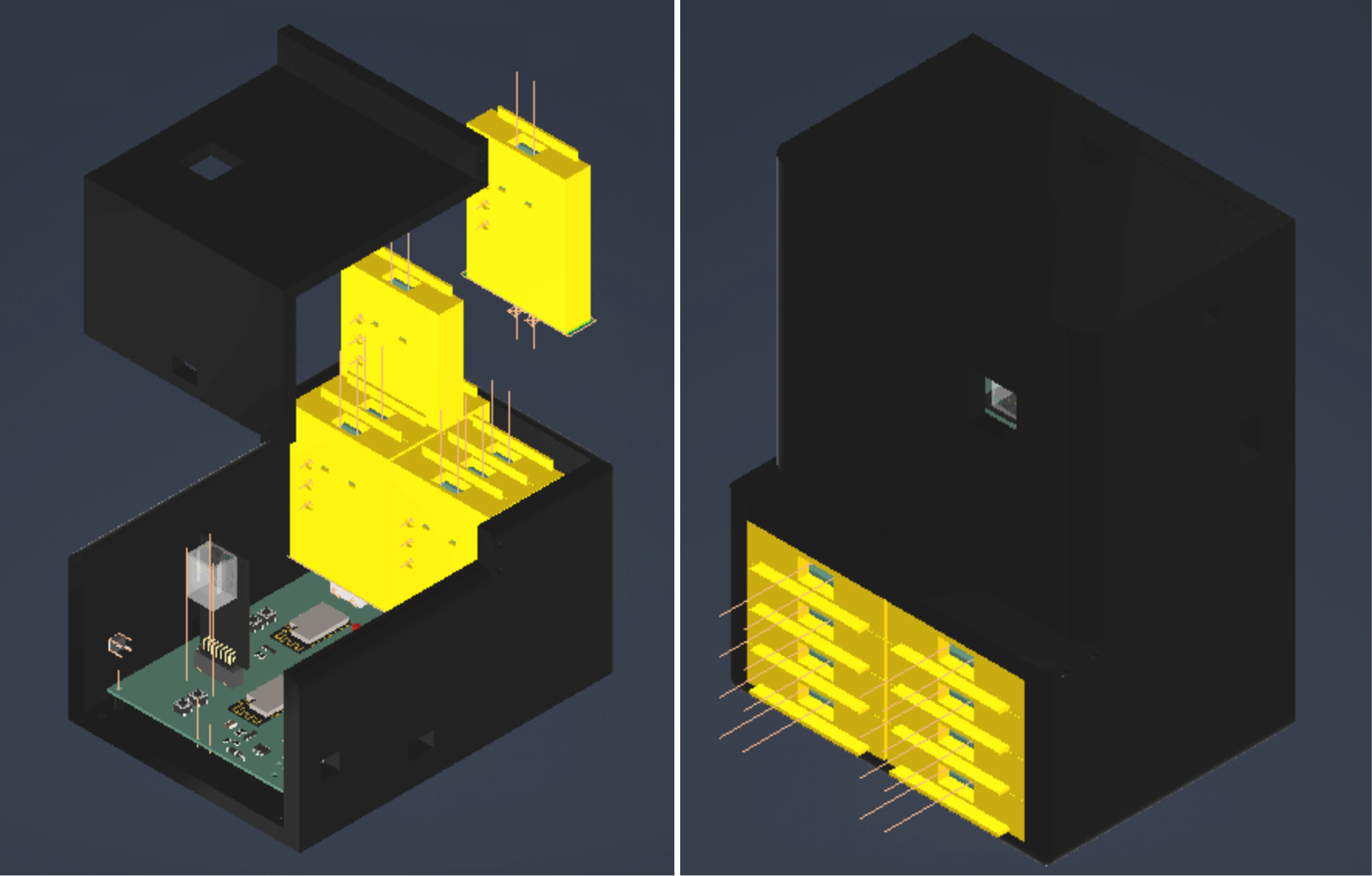
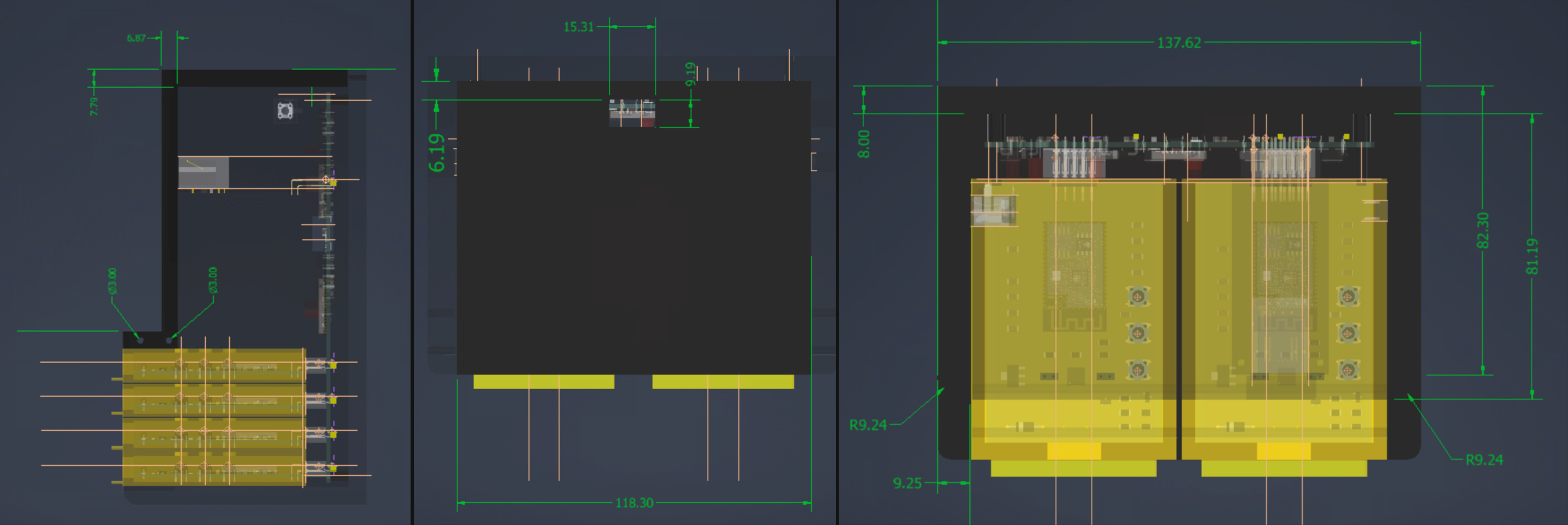
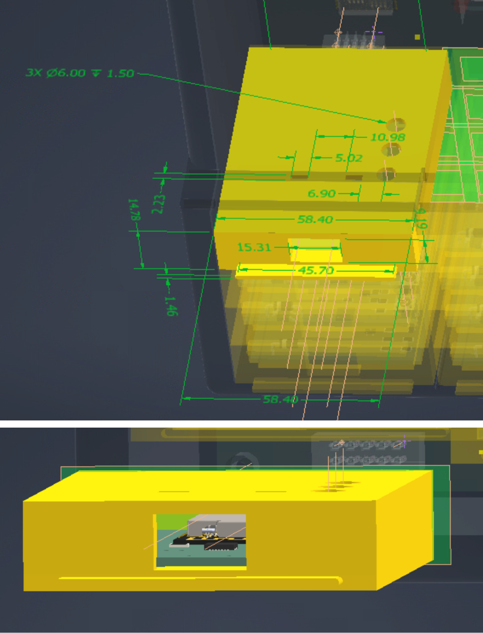
The physical enclosure consists of six piece types, along with an optional divider: 1x Enclosure Lid, 1x Enclosure Base, 8x compute Enclosures, 8x compute Enclosure Lids, 6x 3mm diameter - 20mm screws, 4x 3mm diameter - 5 mm screws. You can find the related CAD files at /cad/ w/o dependencies. Reach out to Aneesh Poddutur for more information.
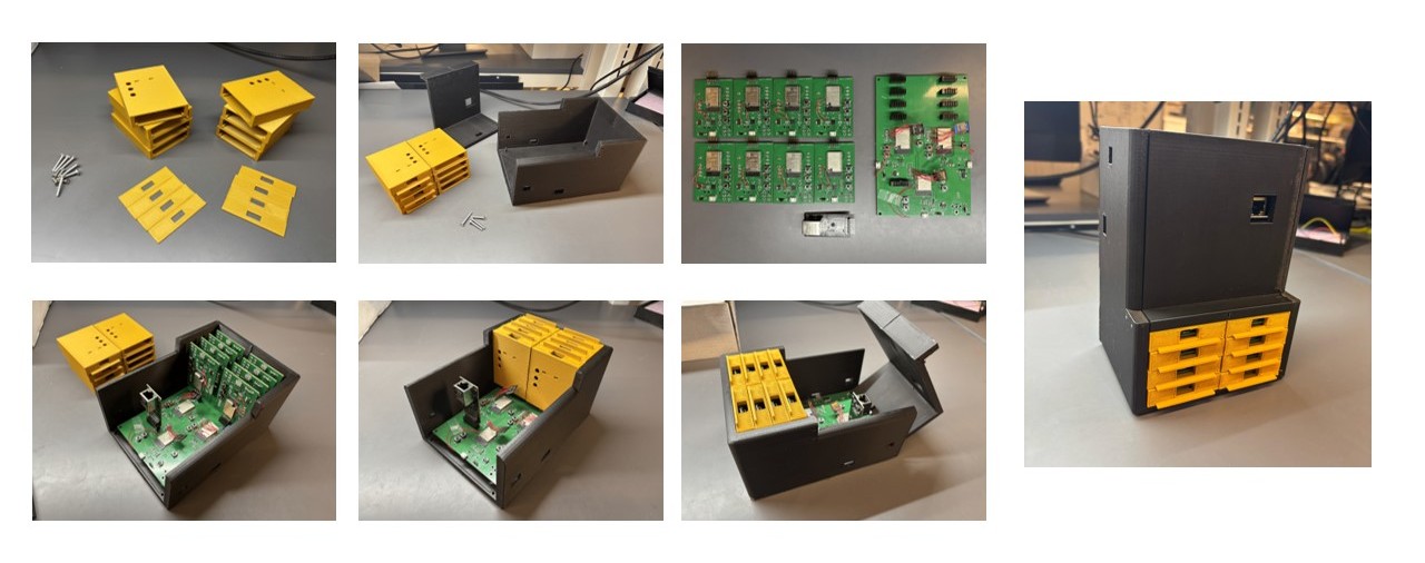
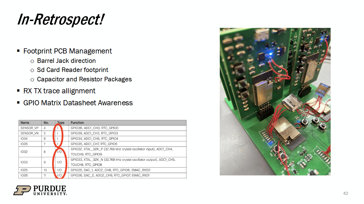
This was our first time working on PCB Design, and had a few fly-wires hanging about. Below is one of the slides we usd in our Final Presentation to sound endearing ;)
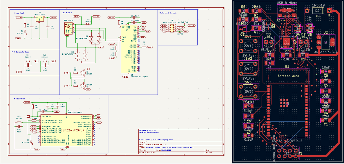
You can find our PCB Designs at /gerbers/ and /kicad_projects! Reach out to Gautam Nambiar and Gokul Harikrishnan if you have any questions.
All the code for the MCUs are maintained within the /src folder. Each node's build is maintained within it's own ESP-IDF setup, and can be configured in isolation. /model_train contains the code for training the models and preparing weights to flashed through ./compute_nodes. Please reach out to Akshath Raghav if you have any questions!
make venv; make setup; make run.idf.py configured and IDF_PATH set up. Remember, idf.py should be run in an ESP-IDF project directory, i.e., a directory containing a CMakeLists.txt file. idf.py fullclean; idf.py build; idf.py flash -port /dev/ttyUSB1 will be sufficient.| Qty | Value | Footprint | References |
|---|---|---|---|
| 18 | 0.1uF | Capacitor_SMD:C_1206_3216Metric_Pad1.33x1.80mm_HandSolder | C1, C10, C12, C14, C15, C17, C19, C21, C23, C24, C26, C28, C30, C32, C33, C35 +2 |
| 12 | 10k | Resistor_SMD:R_1206_3216Metric_Pad1.30x1.75mm_HandSolder | R3, R4, R8, R9, R11, R12, R16, R17, R19, R20, R24, R27 |
| 9 | 22uF | Capacitor_SMD:C_1206_3216Metric_Pad1.33x1.80mm_HandSolder | C7, C11, C13, C16, C20, C22, C25, C31, C34 |
| 9 | SW_Push | Button_Switch_THT:SW_PUSH_6mm | SW1, SW2, SW3, SW4, SW5, SW6, SW7, SW9, SW10 |
| 8 | Conn_02x05_Odd_Even | Connector_PinHeader_2.54mm:PinHeader_2x05_P2.54mm_Vertical | S0_Comp_0, S0_Comp_1, S0_Comp_2, S0_Comp_3, S1_Comp_0, S1_Comp_1, S1_Comp_2, S1_Comp_3 |
| 6 | SS8050 | Package_TO_SOT_SMD:SOT-23 | Q1, Q2, Q3, Q4, Q5, Q6 |
| 4 | 10uF | Capacitor_SMD:C_1206_3216Metric_Pad1.33x1.80mm_HandSolder | C2, C9, C18, C27 |
| 4 | 1N5819 | Diode_THT:D_DO-41_SOD81_P10.16mm_Horizontal | D2, D3, D4, D6 |
| 4 | 360 | Resistor_SMD:R_1206_3216Metric_Pad1.30x1.75mm_HandSolder | R2, R18, R26, R28 |
| 3 | 22.1k | Resistor_SMD:R_1206_3216Metric_Pad1.30x1.75mm_HandSolder | R5, R13, R21 |
| 3 | 2k | Resistor_SMD:R_1206_3216Metric_Pad1.30x1.75mm_HandSolder | R7, R15, R23 |
| 3 | 47.5k | Resistor_SMD:R_1206_3216Metric_Pad1.30x1.75mm_HandSolder | R6, R14, R22 |
| 3 | AMS1117-3.3 | Package_TO_SOT_SMD:SOT-223-3_TabPin2 | U1, U2, U6 |
| 3 | Blue LED | LED_THT:LED_D4.0mm | D7, D8, D10 |
| 3 | CP2102N-Axx-xQFN28 | Package_DFN_QFN:QFN-28-1EP_5x5mm_P0.5mm_EP3.35x3.35mm | U5, U10, U15 |
| 3 | PESD5V0L2BT | Diode_SMD:SOT23_NXP-M | U4, U9, U14 |
| 3 | USB_B_Micro | Connector_USB:USB_Micro-B_Amphenol_10118193-0002LF_Horizontal | J1, J2, J3 |
| 2 | ESP32-WROVER-E | PCM_Espressif:ESP32-WROVER-E | S0, S1 |
| 1 | 4.7k | Resistor_SMD:R_1206_3216Metric_Pad1.30x1.75mm_HandSolder | R25 |
| 1 | Barrel_Jack | Connector_BarrelJack:BarrelJack_CUI_PJ-063AH_Horizontal_CircularHoles | J5 |
| 1 | Conn_02x07_Odd_Even | Connector_PinHeader_2.54mm:PinHeader_2x07_P2.54mm_Vertical | J4 |
| 1 | ESP32-WROOM-E | PCM_Espressif:ESP32-WROOM-32E | U3 |
| 1 | N_Micro_SD_Card | Connector_Samtec_MicroPower:Samtec_UMPS-07-XX.X-X-V-S_1x07_P2.0mm_Socket | J7 |
| 1 | RED LED | LED_THT:LED_D4.0mm | D1 |
| 1 | S0_Micro_SD_Card | Connector_Samtec_MicroPower:Samtec_UMPS-07-XX.X-X-V-S_1x07_P2.0mm_Socket | J8 |
| 1 | S1_Micro_SD_Card | Connector_Samtec_MicroPower:Samtec_UMPS-07-XX.X-X-V-S_1x07_P2.0mm_Socket | J6 |
AkshathRaghav/boilernet
Code release for BoilerNet, demo'd at SPARK S'25 as a Purdue Senior Design Capstone. Associated PCB Design and 3D Prints within.


lhr-solar/PS-BPSLeader
Reads voltage, temperature, and current of the main battery pack from the Segment Monitoring Board and HV Carrier boards to ensure the battery remains in a safe state.


cmumford/cap-touch-starter
Simple ESP32 based board design supporting a capacitive touch screen
It measures 111 × 171 mm and has 4 copper layers, 1.6 mm thick.
108 parts, built around the ESP32-WROVER-E(4MB), AMS1117-3.3, PESD5V0L2BT and SS8050. The full list of its parts is on this page, with links to each part's symbol and footprint where PCBKit's library has them.
From the AkshathRaghav/boilernet repository on GitHub, at the commit this page was made from: the board is kicad_projects/network_and_switch_mainboard/Network_and_Switch.kicad_pcb and its schematic kicad_projects/compute_nodes/Compute Node.kicad_sch. PCBKit opens the board in the browser, with nothing to install.
Its repository publishes it under the Apache-2.0 licence: you may reuse it on that licence's terms (keep the author's notice, and for a copyleft licence share your changes alike).