4 layers50 × 60 mm
EPICS Connect4
williamlin108/Klondike-Connect-4---2026
Electronics Repo for Purdue EPICs Klondike Team, DL: William Lin
84 parts1

 AdamTuraj/PicoMMU13
A Klipper expansion board intended to run a MMU unit to control a stepper motor and servo.
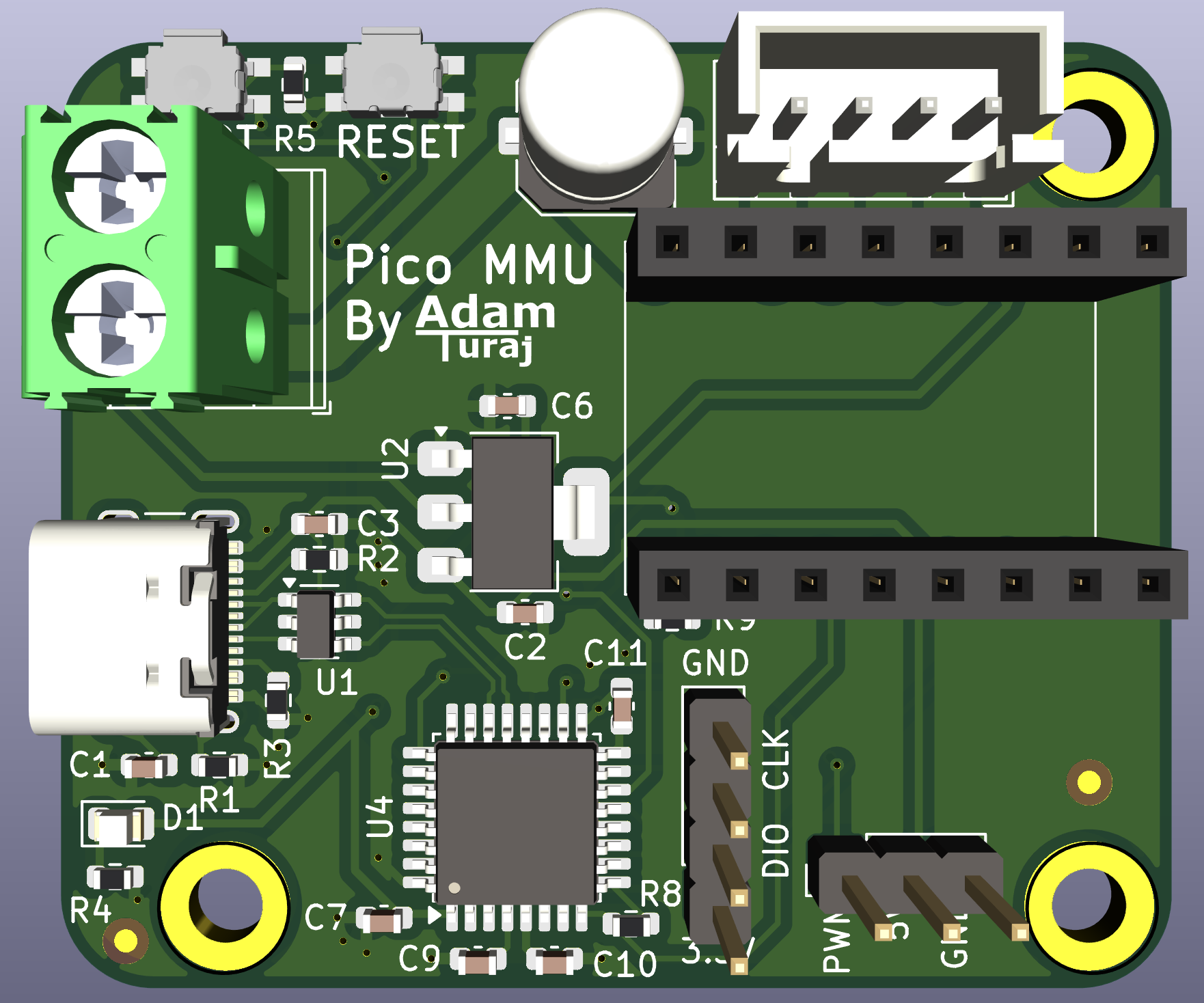
PicoMMUBoard is an open-source printed circuit board by AdamTuraj, from the AdamTuraj/PicoMMU repository on GitHub, published under the MIT licence. It is a 2-layer board of 48 × 40.9 mm with 35 parts on 44 nets, routed with 246 tracks and 40 vias.
It is built around the AMS1117-3.3, USBLC6-2SC6 and TMC2209. Its parts include 9 capacitors, 7 resistors, 6 connectors, 3 ICs and 2 switches. It belongs with the robots and motor control boards and the STM32 boards of this library.


PicoMMU is a PCB designed to control a stepper motor and servo for a multi-material unit. It is compatible with Klipper firmware.
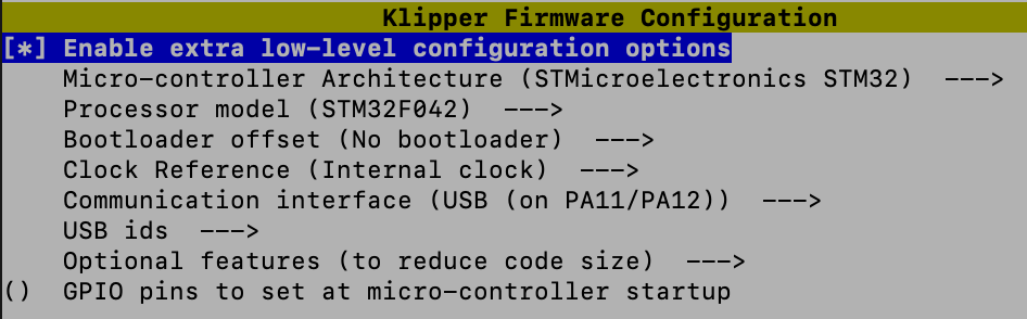
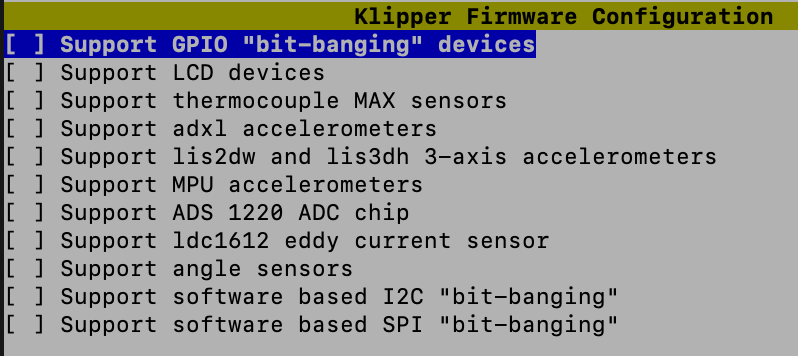
make flash FLASH_DEVICE=xxxx:xxxx.ls /dev/serial/by-id/*.This project is licensed under the MIT License.
| Qty | Value | Footprint | References |
|---|---|---|---|
| 5 | 0.1uF | Capacitor_SMD:C_0603_1608Metric | C3, C7, C9, C10, C11 |
| 2 | 10k | Resistor_SMD:R_0603_1608Metric | R5, R9 |
| 2 | 5k1 | Resistor_SMD:R_0603_1608Metric | R2, R3 |
| 1 | 100uF | Capacitor_SMD:C_Elec_6.3x7.7 | C13 |
| 1 | 10nF | Capacitor_SMD:C_0603_1608Metric | C1 |
| 1 | 10uF | Capacitor_SMD:C_0603_1608Metric | C2 |
| 1 | 1M | Resistor_SMD:R_0603_1608Metric | R1 |
| 1 | 1k | Resistor_SMD:R_0603_1608Metric | R8 |
| 1 | 220R | Resistor_SMD:R_0603_1608Metric | R4 |
| 1 | 22uF | Capacitor_SMD:C_0603_1608Metric | C6 |
| 1 | AMS1117-3.3 | Package_TO_SOT_SMD:SOT-223-3_TabPin2 | U2 |
| 1 | BOOT | Button_Switch_SMD:SW4_KMS-P | SW2 |
| 1 | Conn_Stepper | Connector_JST:JST_XH_B4B-XH-A_1x04_P2.50mm_Vertical | J6 |
| 1 | GREEN | LED_SMD:LED_0805_2012Metric | D1 |
| 1 | LOGO | Symbol:Logo | G*** |
| 1 | PWR | TerminalBlock_MetzConnect:TerminalBlock_MetzConnect_Type073_RT02602HBLU_1x02_P5.08mm_Horizontal | J2 |
| 1 | RESET | Button_Switch_SMD:SW4_KMS-P | SW1 |
| 1 | STLink | Connector_PinHeader_2.54mm:PinHeader_1x04_P2.54mm_Vertical | J3 |
| 1 | STM32F042K6Tx | Package_QFP:LQFP-32_7x7mm_P0.8mm | U4 |
| 1 | Servo Conn | Connector_PinHeader_2.54mm:PinHeader_1x03_P2.54mm_Vertical | J5 |
| 1 | TMC2209 | PicoMMU:TMC2209 | J4 |
| 1 | USBLC6-2SC6 | Package_TO_SOT_SMD:SOT-23-6 | U1 |
| 1 | USB_C | Connector_USB:USB_C_Receptacle_GCT_USB4105-xx-A_16P_TopMnt_Horizontal | J1 |
The 29 most common of 35 parts.
williamlin108/Klondike-Connect-4---2026
Electronics Repo for Purdue EPICs Klondike Team, DL: William Lin


AMOVFC/PanTilt
Three projects live in this folder. They share NewLibrary.kicadsym, TMC2209.pretty and the same philosophy: nothing on the board needs precision placement, every active part is a module in a socket.


creapunk/CLN-ClosedLoopNemaDriver
Compact closed-loop stepper motor driver designed for NEMA motors


wntrblm/jellyfish-and-starfish
Jellyfish and Starfish are control boards designed for use with the LumenPnP. Starfish controls the base of the machine including X & Y axes and pneumatics.
It measures 48 × 40.9 mm and has 2 copper layers, 1.6 mm thick.
35 parts, built around the AMS1117-3.3, USBLC6-2SC6 and TMC2209. The full list of its parts is on this page, with links to each part's symbol and footprint where PCBKit's library has them.
From the AdamTuraj/PicoMMU repository on GitHub, at the commit this page was made from: the board is Kicad/PicoMMUBoard.kicad_pcb and its schematic Kicad/PicoMMUBoard.kicad_sch. PCBKit opens the board in the browser, with nothing to install.
Its repository publishes it under the MIT licence: you may reuse it on that licence's terms (keep the author's notice, and for a copyleft licence share your changes alike).