4 layers118.4 × 131 mm
Nifty Numpad before sockets
Acliad/Nifty-Numpad
Full sized numpad with an extra row and two extra columns of macro keys. It was created as a companion to my TKL keyboard for CAD design.
175 parts

 Acliad/Nifty-Numpad
Full sized numpad with an extra row and two extra columns of macro keys. It was created as a companion to my TKL keyboard for CAD design.
Nifty Numpad is an open-source printed circuit board by Acliad, from the Acliad/Nifty-Numpad repository on GitHub. It is a 2-layer board of 118.4 × 129.7 mm with 176 parts on 124 nets, routed with 998 tracks and 854 vias.
It is built around the RP2040, W25Q40CLSNIG and SN74LVC1T45DCK, with the SK6812MINI-E and ABLS-12.000MHZ-B4-T among its other parts. Its parts include 66 diodes, 52 capacitors, 35 switches, 8 resistors and 5 ICs. It belongs with the keyboards and input boards and the RP2040 boards of this library.


Nifty Numpad is a full sized numpad with an extra row and two extra columns of macro keys. It was created because I wanted a companion to my TKL keyboard for work. My main workflow involves heavy use of ECAD programs, so the design was tailored for that, but it is generic enough to be nice for many workflows!
The main features are:
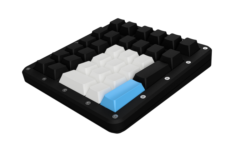
All of the files needed to build this numpad are in this repo (with software as a submodule and in the main QMK repo). The total BOM cost will be somewhere around $65-$85 shipped, but depends heavily on where and how you source things like switches, keycaps, plate, etc. For example, I bought 120x switches, but if you could get 33 switches for cheaper, you might save ~$10.
The most difficult part of the build is soldering the RP2040 (microcontroller used) and associated components. It is highly recommended that you have the PCBs assembled. The files are in this repo for getting the PCB assembled through JLC PCB. You may save some money by soldering some of the components yourself (especially the sockets and LEDs). However, if you just love to solder this can be done with a stencil and plenty of time. I should know 🥲
You can choose to omit the LEDs if you're not into that sort of thing. It'll save you a few bucks.
Parts marked as (DNF) in the BOM are not meant to be populated. If you want easy debugging for software development, you can populate R103, SW101, and SW102.
To have the PCB assembled:
To Solder the PCB assembly yourself:
This case was initially designed to be 3D printed on a resin printer, but it actually prints best on an FDM printer. There are not special instructions here. You can either print the case yourself or have it printed using a service. JLC offers printing of many varieties. This might be a good choice if you're already ordering the PCB from them.
All the screw holes are designed to be tapped by a self-tapping screw. The BOM has some recommendations for some plastic-threading screws.
I have added a "shadow line" to the case outline. There's a top-case print option with and without this line. I think it helps the look a bit for FDM prints, but it's up to you.
It helps the sound profile considerably to fill up the case with some kind of dampening material. You could use foam or pour castable silicone into the case (I used this one). You can (and probably should) pour the silicone directly into the case. However, I've also included a mold for this in the Mechanical folder.
I used plate-mount switches on this design. You can either make your own plate or have one made for you. There's a model of the plate as well as a DXF file in the Mechanical folder. Here is some information about some options:
Whatever you choose to do, you should find appropriate files in the Mechanical folder.
The fun part! Choose your favorite Cherry MX compatible switches and pop them in. If you're using LEDs, make sure you get switches with a clear top.
I found it difficult to source backlit keycaps that fit this build well. You might be better off using non-backlit keycaps. There are some AliExpress sellers who will sell portions of a keyboard at a time so you can mix and match colors. This is what I ended up doing, but I couldn't find any in a uniform profile like XDA or DSA. If you find a good source of keycaps, please share!
If you're feeling plush, I think the numpad + icono kits of these keycaps would be really nice.
You'll also need 3x 2u plate-mount stabilizers. You can source these from most keyboard part suppliers or Ali Express.
I've used QMK for this build. Theere are builds for the VIA GUI configurator, a basic default usage, and an example for how to use the "fancy" RGB Idle mode and some tap-dance features. VIA is probably the easiest way to configure the keymap since you can configure it over a GUI, but if you're comfortable with QMK, you can do some cool customizations.
The Nifty Numpad has been merged into the main QMK repo, which you can find here. My personal fork for developing the keyboard software is a submodule of this repo. You can find it here.
QMK and the build/flash process is pretty well document, so I'll leave that to the QMK community. If you have specific issues with the Nifty Numpad, feel free to message me.
| Qty | Value | Footprint | References |
|---|---|---|---|
| 45 | 100nF | Capacitor_SMD:C_0603_1608Metric | C104, C105, C106, C107, C108, C109, C110, C111, C112, C113, C114, C117, C201, C202, C203, C204 +29 |
| 33 | 1N4148 | Diode_SMD:D_SOD-123 | D301, D302, D303, D304, D305, D306, D307, D308, D309, D310, D311, D312, D313, D314, D315, D316 +17 |
| 33 | SK6812MINI-E | irex_LED_SMD:LED_SK6812MINI-E_3.2x2.8mm | D201, D202, D203, D204, D205, D206, D207, D208, D209, D210, D211, D212, D213, D214, D215, D216 +17 |
| 30 | PG1511 | PCM_Switch_Keyboard_Hotswap_Kailh:SW_Hotswap_Kailh_MX_1.00u | SW301, SW302, SW303, SW304, SW305, SW306, SW307, SW308, SW309, SW310, SW311, SW312, SW313, SW314, SW315, SW316 +14 |
| 5 | 6.00mm | irex_MountingHole:MountingHole_6.0mm_ReducedCourtyard | H101, H102, H103, H104, H105 |
| 4 | 1uF | Capacitor_SMD:C_0603_1608Metric | C102, C103, C115, C116 |
| 2 | 1k | Resistor_SMD:R_0603_1608Metric | R103, R108 |
| 2 | 27 | Resistor_SMD:R_0603_1608Metric | R105, R106 |
| 2 | 27pF | Capacitor_SMD:C_0603_1608Metric | C118, C119 |
| 2 | 5.1k | Resistor_SMD:R_0603_1608Metric | R101, R102 |
| 2 | PG1511 | PCM_Switch_Keyboard_Hotswap_Kailh:SW_Hotswap_Kailh_MX_2.00u_90deg | SW318, SW329 |
| 2 | PTS636 SL43 SMTR LFS | irex_Button_Switch_SMD:SW-PUSH-6x3.5mm_CK-PTS636SL43x_HandSolder | SW101, SW102 |
| 1 | 10k | Resistor_SMD:R_0603_1608Metric | R107 |
| 1 | 10uF | Capacitor_SMD:C_0603_1608Metric | C101 |
| 1 | 3.3V | Package_TO_SOT_SMD:SOT-353_SC-70-5 | U101 |
| 1 | 330 | Resistor_SMD:R_0603_1608Metric | R104 |
| 1 | ABLS-12.000MHZ-B4-T | Crystal:Crystal_SMD_HC49-SD | Y101 |
| 1 | CM1213A−02Sx | Package_TO_SOT_SMD:SOT-143 | U102 |
| 1 | IREX_LOGO | irex_Aesthetic:Logo_irex_10.0x11.1mm_Mask | G*** |
| 1 | PG1511 | PCM_Switch_Keyboard_Hotswap_Kailh:SW_Hotswap_Kailh_MX_2.00u | SW332 |
| 1 | RP2040 | Package_DFN_QFN:QFN-56-1EP_7x7mm_P0.4mm_EP3.2x3.2mm | U104 |
| 1 | SN74LVC1T45DCK | Package_TO_SOT_SMD:SOT-363_SC-70-6 | U103 |
| 1 | SWD | Connector_PinHeader_2.54mm:PinHeader_1x05_P2.54mm_Vertical | J101 |
| 1 | UART | Connector_PinHeader_2.54mm:PinHeader_1x04_P2.54mm_Vertical | J103 |
| 1 | USB-C | irex_Connector_USB:USB_C_Receptacle_GCT_USB4105-GF-A-060 | J102 |
| 1 | W25Q40CLSNIG | Package_SO:SOIC-8_3.9x4.9mm_P1.27mm | U105 |
Acliad/Nifty-Numpad
Full sized numpad with an extra row and two extra columns of macro keys. It was created as a companion to my TKL keyboard for CAD design.

Acliad/XBOX-Sign
A "weekend" project converting a vanity Xbox sign to the OG Xbox style

hack-a-tack/FPGA_Logic_Analyzer
(Info applies to rev. 1, update for later revisions (only final rev. matters in the README)) FPGA-based 8-channel logic analyzer implemented on iCE40UP5K.


malcx95/ZeKeyboard
Custom RGB-backlit 3D-printed mechanical keyboards with custom firmware


SirBramble/Loguwu
A slightly modified version of the firmware found in the LogicAnalyzer repository can be found in 03Firmware.
It measures 118.4 × 129.7 mm and has 2 copper layers, 1.63 mm thick.
176 parts, built around the RP2040, W25Q40CLSNIG, SN74LVC1T45DCK and SK6812MINI-E. The full list of its parts is on this page, with links to each part's symbol and footprint where PCBKit's library has them.
From the Acliad/Nifty-Numpad repository on GitHub, at the commit this page was made from: the board is PCB/Main PCB/Nifty Numpad.kicad_pcb and its schematic PCB/Main PCB/Nifty Numpad.kicad_sch. PCBKit opens the board in the browser, with nothing to install.
Its repository states no licence, so its author keeps all rights: ask Acliad before reusing the design.