

2 layers56.6 × 48.6 mm
Water Alarm
ANSHAD134/PCB-Files
A collection of my personal KiCad PCB design projects, custom symbol/footprint libraries, and 3D models used across different electronics builds.
8 parts
 ANSHAD134/PCB-Files
A collection of my personal KiCad PCB design projects, custom symbol/footprint libraries, and 3D models used across different electronics builds.
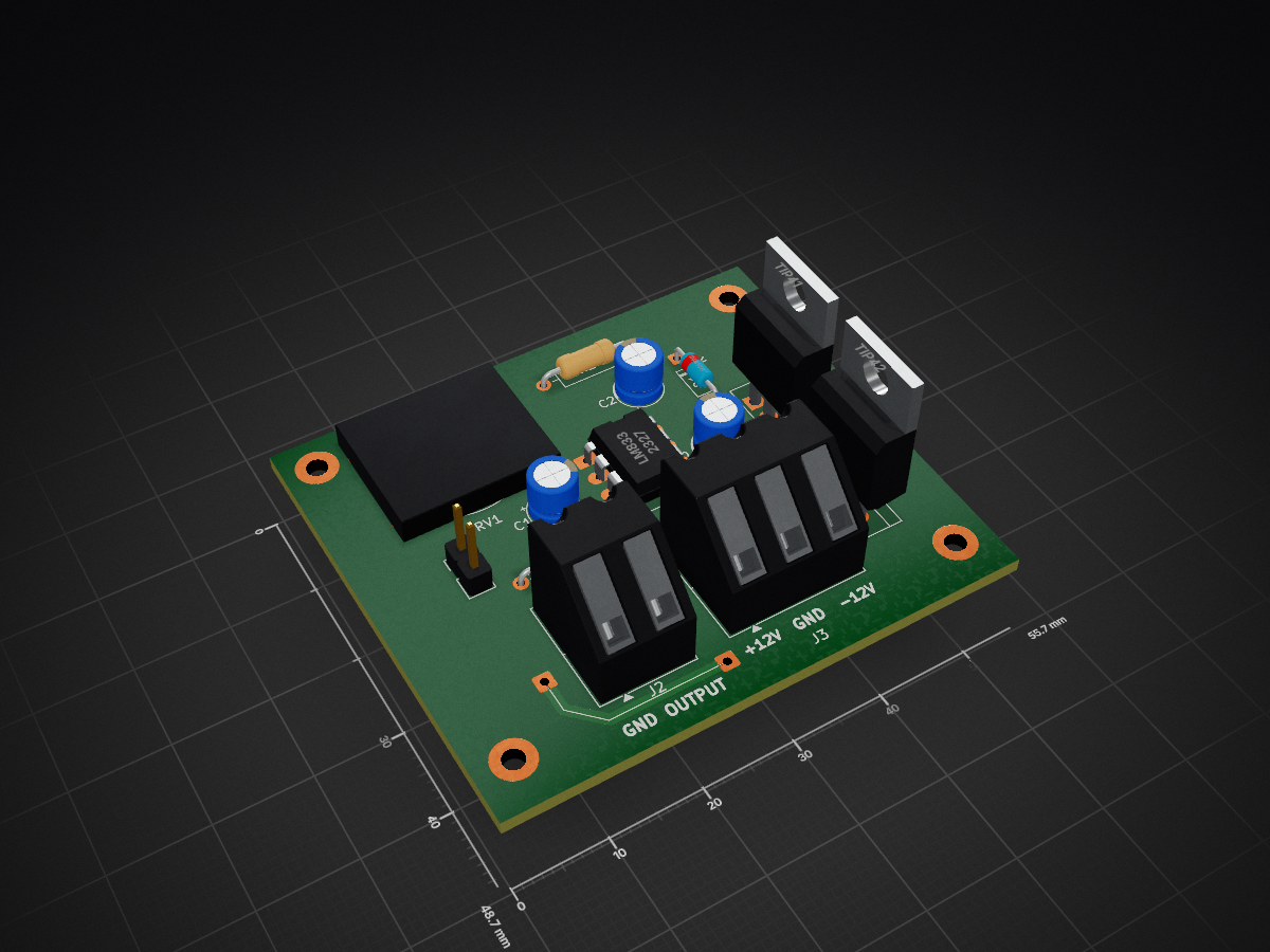
Amplifier is an open-source printed circuit board by ANSHAD134, from the ANSHAD134/PCB-Files repository on GitHub. It is a 2-layer board of 55.7 × 48.7 mm with 20 parts on 10 nets, routed with 114 tracks and 0 vias.
It is built around the TIP41 and TIP42. Its parts include 3 capacitors, 3 connectors, 2 resistors, 2 transistors and 1 IC. It belongs with the audio and music boards of this library.


A collection of my personal KiCad PCB design projects, custom symbol/footprint libraries, and 3D models used across different electronics builds.
PCB-Files/
├── 3D Models/                     # STEP files for 3D-printed / mechanical parts (motors, etc.)
├── KiCad Tools/
│   └── Symbol Libaries/           # Custom KiCad symbol libraries
├── Water Alarm/                   # Water level alarm PCB project (schematic + layout)
│   ├── Water Alarm.kicad_pro
│   ├── Water Alarm.kicad_sch
│   ├── Water Alarm.kicad_pcb
│   ├── FoodPrint Libraries/       # Custom footprints used in the project
│   ├── Graber/                    # Gerber export files
│   └── Water Alarm-backups/       # Auto-generated project backups
└── amplifier/ # Audio amplifier PCB projectA KiCad project for a water level detection alarm circuit — includes schematic, PCB layout, custom footprints, and Gerber files ready for fabrication.
A KiCad-based audio amplifier PCB design.
STEP (.stp) files for components (e.g. gear motors) used to preview real-world fit inside KiCad's 3D viewer.
Custom schematic symbol libraries reused across multiple projects for easier and consistent design work.
git clone https://github.com/ANSHAD134/PCB-Files.git.kicad_pro file in KiCad to view/edit the schematic and PCB layout.Graber/ folders) can be sent directly to a PCB fab (JLCPCB, PCBWay, etc.) for manufacturing.This project is open for personal and educational use. Feel free to fork and modify for your own builds. Add a LICENSE file (e.g. MIT) if you'd like to make the terms official.
ANSHAD134 — GitHub Profile
| Qty | Value | Footprint | References |
|---|---|---|---|
| 4 | MountingHole_2.2mm_M2_Pad | MountingHole:MountingHole_2.2mm_M2_Pad | ., ., ., . |
| 2 | 0.22uF | Capacitor_THT:CP_Radial_D5.0mm_P2.50mm | C1, C3 |
| 1 | 10K | Resistor_THT:R_Axial_DIN0207_L6.3mm_D2.5mm_P10.16mm_Horizontal | R2 |
| 1 | 1M | Resistor_THT:R_Axial_DIN0207_L6.3mm_D2.5mm_P10.16mm_Horizontal | R1 |
| 1 | 1N4148 | Diode_THT:D_DO-35_SOD27_P7.62mm_Horizontal | D1 |
| 1 | 22K | Potentiometer_THT:Potentiometer_Piher_PT-15-V15_Vertical | RV1 |
| 1 | 47uF | Capacitor_THT:CP_Radial_D5.0mm_P2.50mm | C2 |
| 1 | INPUT | Connector_PinHeader_2.54mm:PinHeader_1x02_P2.54mm_Vertical | J1 |
| 1 | LM833 | Package_DIP:DIP-8_W7.62mm_LongPads | U1 |
| 1 | OUTPUT | TerminalBlock_Altech:Altech_AK300_1x02_P5.00mm_45-Degree | J2 |
| 1 | POWER IN | TerminalBlock_Altech:Altech_AK300_1x03_P5.00mm_45-Degree | J3 |
| 1 | TIP41 | Package_TO_SOT_THT:TO-220-3_Vertical | Q1 |
| 1 | TIP42 | Package_TO_SOT_THT:TO-220-3_Vertical | Q2 |
The 17 most common of 20 parts.
ANSHAD134/PCB-Files
A collection of my personal KiCad PCB design projects, custom symbol/footprint libraries, and 3D models used across different electronics builds.

profdc9/FlexibleCharger
An Arduino-controlled charger for different kinds of batteries, or it can be a standalone power supply

promesoft/KicadJE-EuroPowerSupply
Takes a Laptop 19V input and makes +-12 and 5 v out

Markus-Fitz/Protection-board
Speaker-protection board for power amplifier.

MUDAL/Function-Generator
Custom Function Generator designed and developed by Olaoluwa Raji. This project is a complete embedded system solution with both hardware and software implemented by me. Relevant reference materials are included.


oselcukyatagan/CLASS_AB_AUDIO_POWER_AMP
This is the repository for the developing of the class AB audio power amplifier device.
It measures 55.7 × 48.7 mm and has 2 copper layers, 1.6 mm thick.
20 parts, built around the TIP41 and TIP42. The full list of its parts is on this page, with links to each part's symbol and footprint where PCBKit's library has them.
From the ANSHAD134/PCB-Files repository on GitHub, at the commit this page was made from: the board is amplifier/amplifier.kicad_pcb and its schematic NE555 LED Flasher – KiCad PCB Design/NE555 LED Flasher – KiCad PCB Design.kicad_sch. PCBKit opens the board in the browser, with nothing to install.
Its repository states no licence, so its author keeps all rights: ask ANSHAD134 before reusing the design.