

4 layers149 × 95 mm
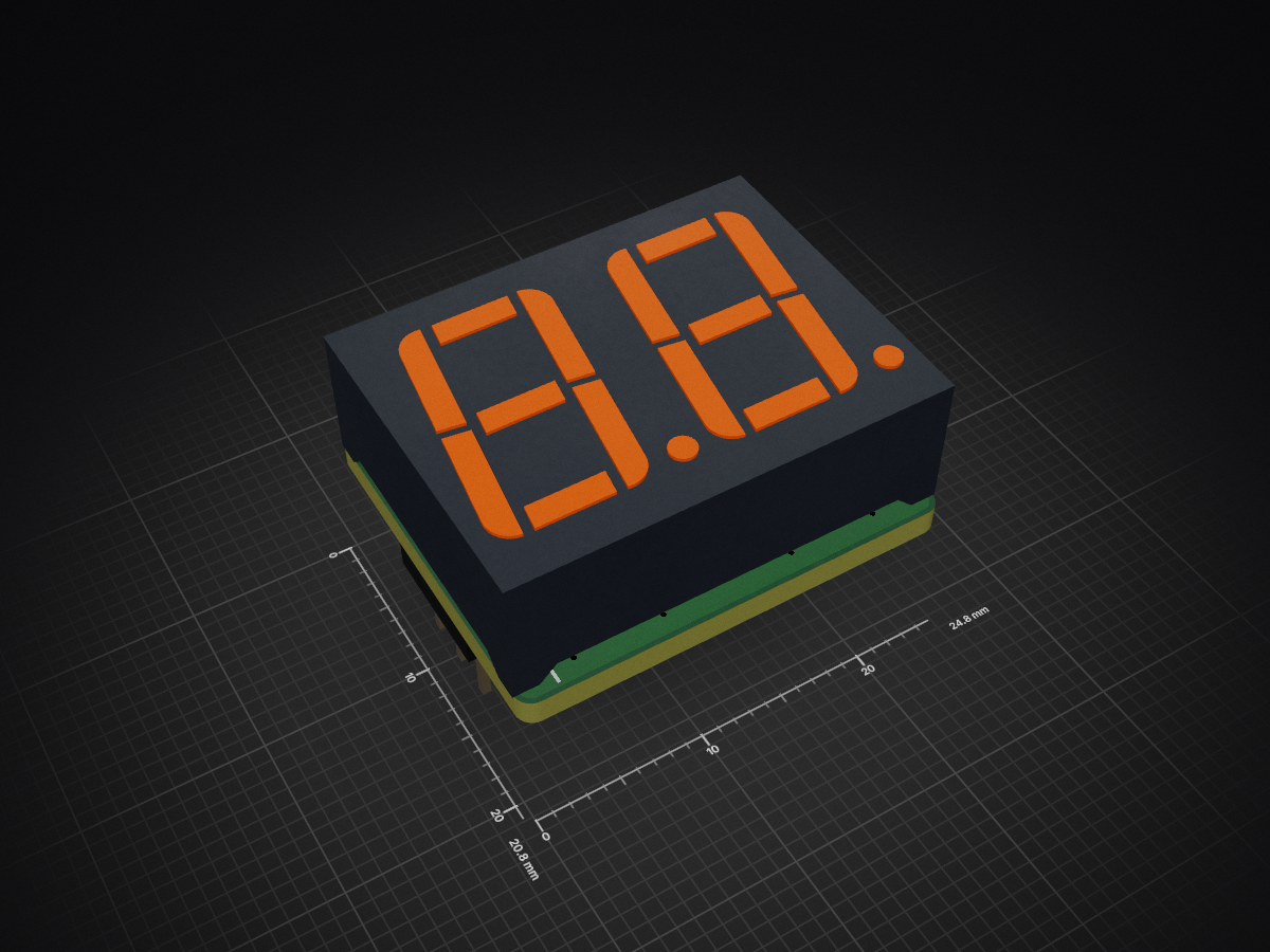
A 14 Segment LED Display module - receives UART ASCII Data, with daisy chain capability. Built on the CH32V003
MkI is an open-source printed circuit board by ADBeta, from the ADBeta/00314S2D-ASCII_Display_Module repository on GitHub, published under the MIT licence. It is a 2-layer board of 24.8 × 20.8 mm with 16 parts on 42 nets, routed with 167 tracks and 28 vias.
It is built around the AO3400A. Its parts include 3 transistors, 2 capacitors, 2 resistors, 2 connectors and 1 IC. It belongs with the lEDs and displays and interfaces and adapters boards and the RISC-V boards of this library.
00314S2D-ASCII is a Daisychain-able 14 Segment, 2 Digit Display Module,
designed around the CH32V003 MCU.
It receives 115200 Baud UART Data, in standard ASCII Format, then displays
up to 2 Chars per Module. Any Additional chars will be transmitted down the
chain of displays.
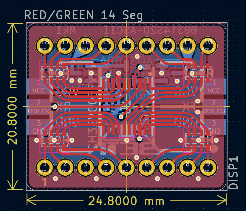
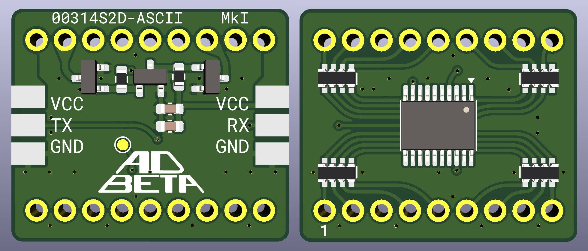
Connect a standard UART TX line, running at 115200 Baud to the
RX connection of the module, it is now ready to accept data.
Any ASCII characters will be printed to the display, when one displays
buffer is full, it will echo the data on to the next display.
Transmit \n or \r to clear the displays, this will propegate and
clear all displays at once.
To Daisychain the displays, connect TX from one, to RX of the next,
along with VCC and GND - this will allow you to connect [theoretically]
infinite displays in one chain, the only limit being current on VCC.
BOM
RN1        330R 4*0603 Resistor Array
RN2        330R 4*0603 Resistor Array
RN3        330R 4*0603 Resistor Array
RN4        330R 4*0603 Resistor Array
R1         10R 0603
R2         2K2 0603
Q1         AO3400 N-Ch MOSFET SOT-23
Q2         AO3400 N-Ch MOSFET SOT-23
Q3         AO3400 N-Ch MOSFET SOT-23
C1         100nF 0603 MLCC
C2         1uF 0603 MLCC
U1         CH32V003FxPx TSSOP-20
DISP1      Red/Green/Blue 14 Segment 2 Digit Common Cathode Display
Programming is done via the SWIO TestPoint on the back of the PCB. Once programmed, SWIO is disabled to be used as a normal GPIO. To Reprogram the deivce, connect a programmer to the SWIO pin, and power cycle the device - this will put the device into program mode.
minichlink -D to allow NRST to be a GPIO PinNOTE: make will do both of these steps automatically if the user
chooses to use that toolchain
[TODO] Make MkII PCB with better programming ports
Make MkII PCB have MCU and resistors on rear side for easier repair (?)
Build automatic testing jig to validate modules before displays are attached
Investigate segment failure issue
MIT License Copyright (c) 2024 ADBeta
| Qty | Value | Footprint | References |
|---|---|---|---|
| 4 | 150R | Resistor_SMD:R_Array_Convex_4x0603 | RN1, RN2, RN3, RN4 |
| 3 | AO3400A | Project_Footprints:SOT-23_Clean | Q1, Q2, Q3 |
| 1 | 100nF | Capacitor_SMD:C_0603_1608Metric | C1 |
| 1 | 10R | Resistor_SMD:R_0603_1608Metric | R1 |
| 1 | 1uF | Capacitor_SMD:C_0603_1608Metric | C2 |
| 1 | 2K2 | Resistor_SMD:R_0603_1608Metric | R2 |
| 1 | CH32V003FxPx | Package_SO:TSSOP-20_4.4x6.5mm_P0.65mm | U1 |
| 1 | Conn_RX | Project_Footprints:Conn_Daisy_Chain | J1 |
| 1 | Conn_TX | Project_Footprints:Conn_Daisy_Chain | J2 |
| 1 | RED/GREEN 14 Seg | Project_Footprints:14_Seg_2_Digit_Display | DISP1 |
| 1 | SWIO | TestPoint:TestPoint_Pad_D1.0mm | TP1 |


brickbots/PiFinder
A plate solving telescope finder based around a Raspberry PI and RPI HQ Camera


MickiusMousius/Rolio46Keyboard
A split wireless keyboard based on the Corne and Sofle
It measures 24.8 × 20.8 mm and has 2 copper layers, 1.6 mm thick.
16 parts, built around the AO3400A. The full list of its parts is on this page, with links to each part's symbol and footprint where PCBKit's library has them.
From the ADBeta/00314S2D-ASCII_Display_Module repository on GitHub, at the commit this page was made from: the board is PCB/MkI/MkI.kicad_pcb and its schematic PCB/MkI/MkI.kicad_sch. PCBKit opens the board in the browser, with nothing to install.
Its repository publishes it under the MIT licence: you may reuse it on that licence's terms (keep the author's notice, and for a copyleft licence share your changes alike).