4 layers123.8 × 362.3 mm

 65roadster/TinyBench-Pico
A Raspberry Pi Pico Breakout Board with Dual Channel DAC
Rpi platform r1 is an open-source printed circuit board by 65roadster, from the 65roadster/TinyBench-Pico repository on GitHub. It is a 2-layer board of 98.4 × 98.4 mm with 55 parts on 37 nets, routed with 380 tracks and 34 vias.
It is built around the LM4040D33FTA, MBR120VLSFT1G-TP and TL3305BF260QG. Its parts include 33 connectors, 5 capacitors, 5 resistors, 3 ICs and 2 switches. It belongs with the RP2040 boards of this library.


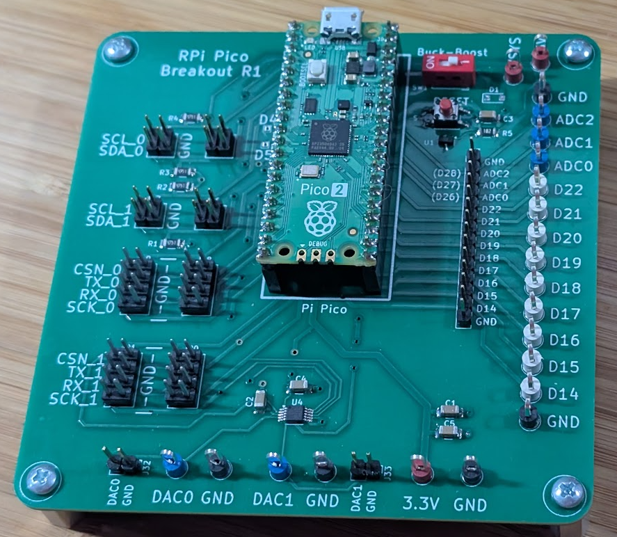
This is simply a breakout that has been optimized for my workflow, not to have a cheap product on amazon.
Integrated precision 3.3V reference using the LM4040D33 Dual channel DAC using the MCP48FVBXX (8/10/12 bit options are available) Dual 2x4 headers each for SPI0 and SPI1, allowing jumper to a daughterboard and monitor using a logic analyzer Dual 2x2 headers each for I2C0 and I2C1, allowing jumper to a daughterboard and monitor using a logic analyzer On-board reset to factilite putting into BOOTSEL mode without unplugging the USB cable DIP switch to disable on-board VUSB->3.3V converter, to allow powering from a low-noise source Keystone test points and 0.1" header pins for GPIO and ADC
code directory has several examples using the Pico 2blink, Arduino IDE, blinks the onboard LEDDAC_8bit, Arduino IDE, demostrates using the 8 bit version of the DACDAC_12bit, Arduino IDE, demostrates using the 12 bit version of the DACMCP4141_Breakout_Test, Arduino IDE, demonstrates use of the MCP4141TMP1075, Arduino IDE, demonstrates use of the TMP1075| Qty | Value | Footprint | References |
|---|---|---|---|
| 9 | 5012 | 1-rpi-footprints:Keystone-5012 | J1, J2, J3, J4, J5, J6, J7, J8, J9 |
| 5 | 5011 | 1-rpi-footprints:Keystone-5011 | J23, J25, J27, J29, J31 |
| 5 | 5127 | 1-rpi-footprints:Keystone-5127 | J10, J11, J12, J28, J30 |
| 4 | 1uF | Capacitor_SMD:C_1206_3216Metric_Pad1.33x1.80mm_HandSolder | C1, C2, C3, C4 |
| 4 | 4.7k | Resistor_SMD:R_1206_3216Metric_Pad1.30x1.75mm_HandSolder | R1, R2, R3, R4 |
| 4 | Conn_I2C_2x2_2.54mm | Connector_PinHeader_2.54mm:PinHeader_2x02_P2.54mm_Vertical | J14, J15, J16, J17 |
| 4 | Conn_SPI_2x4_2.54mm | Connector_PinHeader_2.54mm:PinHeader_2x04_P2.54mm_Vertical | J18, J19, J20, J21 |
| 4 | MountingHole | 1-rpi-footprints:Mount-Hole-#6-NoPad | MTH1, MTH2, MTH3, MTH4 |
| 3 | 5010 | 1-rpi-footprints:Keystone-5010 | J22, J24, J26 |
| 2 | Header 1x2 | Connector_PinHeader_2.54mm:PinHeader_1x02_P2.54mm_Vertical | J32, J33 |
| 2 | TestPoint | TestPoint:TestPoint_THTPad_1.0x1.0mm_Drill0.5mm | TP1, TP2 |
| 1 | 1.8k | Resistor_SMD:R_1206_3216Metric_Pad1.30x1.75mm_HandSolder | R5 |
| 1 | 10uF | Capacitor_SMD:C_1206_3216Metric_Pad1.33x1.80mm_HandSolder | C5 |
| 1 | DIP_SPST | Button_Switch_THT:SW_DIP_SPSTx01_Slide_6.7x4.1mm_W7.62mm_P2.54mm_LowProfile | SW1 |
| 1 | Header 14 pin | Connector_PinHeader_2.54mm:PinHeader_1x14_P2.54mm_Vertical | J13 |
| 1 | LM4040D33 | Package_TO_SOT_SMD:SOT-23 | U1 |
| 1 | MBR120VLSFT1G | Diode_SMD:D_SOD-123F | D1 |
| 1 | MCP48FVBXX | 1-rpi-footprints:MSOP-10_3x3mm_P0.5mm | U4 |
| 1 | Pi Pico 2 | 1-rpi-footprints:PICO_2_RP2350 | U2 |
| 1 | TL3305BF260QG | 1-rpi-footprints:SO_260QG_EWI | SW2 |
It measures 98.4 × 98.4 mm and has 2 copper layers, 1.6 mm thick.
55 parts, built around the LM4040D33FTA, MBR120VLSFT1G-TP and TL3305BF260QG. The full list of its parts is on this page, with links to each part's symbol and footprint where PCBKit's library has them.
From the 65roadster/TinyBench-Pico repository on GitHub, at the commit this page was made from: the board is rpi-platform-r1.kicad_pcb and its schematic rpi-platform-r1.kicad_sch. PCBKit opens the board in the browser, with nothing to install.
Its repository states no licence, so its author keeps all rights: ask 65roadster before reusing the design.


martinroger/ipodesp32
An iPod emulator for 2006-2013 BMW Mini Coopers that need Bluetooth


sabogalc/project-piCo
Because it should be a crime to release a product with Micro-USB in the 2020s

ShawnHymel/rpi-pico-debugger-shoe
Stackable debugger board for the Raspberry Pi Pico. Solder long headers to this debugger board in order to connect the Pico to it.

