4 layers401.5 × 130.1 mm

 4rynv/Eklavya_Gantry12
an attempt to automate screwing out and in of screw holes arranged in a matrix formation
Gantry PCBv2 is an open-source printed circuit board by 4rynv, from the 4rynv/Eklavya_Gantry repository on GitHub, published under the MIT licence. It is a 2-layer board of 190.5 × 121.8 mm with 173 parts on 199 nets, routed with 1,153 tracks and 102 vias.
It is built around the 74HC245D, ESP32-WROOM-32U and MP1584EN, with the SN74CBT3244DW, TLV75733PDBV and SS14 among its other parts. Its parts include 55 resistors, 30 capacitors, 17 diodes, 17 connectors and 13 ICs. It belongs with the ESP32 boards of this library.


 |  |
|---|
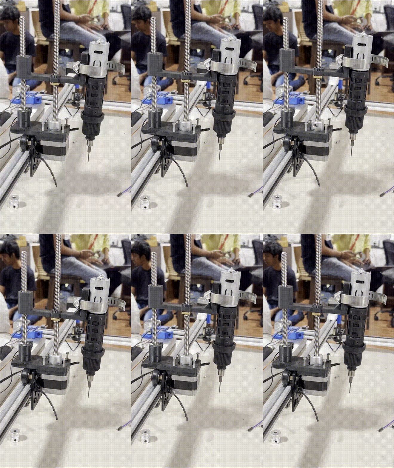
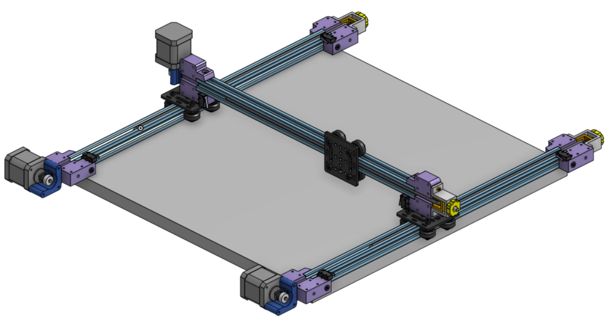
GantryMate-200 addresses the challenge of automating the precise handling of ~280 miniature screws (1 mm size) on sensitive LED panels. The system must operate with extreme precision around delicate circuitry while maintaining high-speed performance.
An advanced automated gantry system designed for precision screwing and unscrewing of miniature screws on delicate LED panels with sub-millimeter accuracy and high-speed operation.
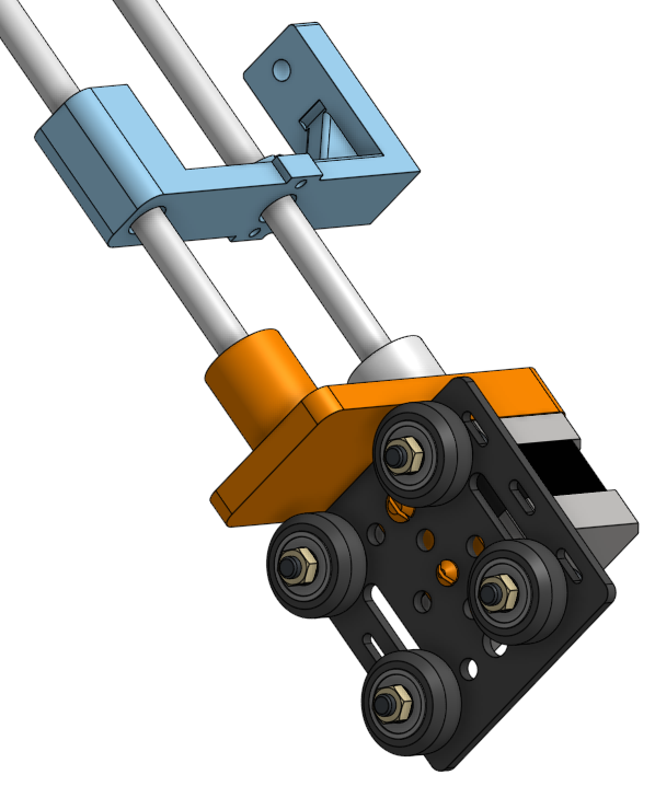
CAD MODEL (Our CAD files)
The target LED panel consists of two distinct layers:
Installation Process: Follows reverse order (bottom layer first, then top layer)
Given the proximity to sensitive circuitry, the system must ensure:
Hardware requirements:
Software used:
Eklavya_Gantry
├── Docs/
├── Firmware/
│   ├── DRV8825/                   #Code for Running the system on DRV8825
│   │   ├── circle/
│   │   ├── Double_axes/
│   │   ├── final/
│   │   ├── go_to_pos/
│   │   ├── homing/
│   │   ├── limit/
│   │   ├── SRA/
│   │   ├── step_func/
│   │   ├── stepper_test/
│   │   ├── totalhoming/
│   │   └── total_positioning/
│   ├── TMC2208/                   #Code for Running the system on TMC2208
│   │   ├── Go_to_pos/
│   │   ├── step_func/
│   │   └── uart/
│   │       ├── nmea0183_parser/
│   │       ├── uart_async_rxtxtasks/
│   │       ├── uart_echo/
│   │       ├── uart_echo_rs485/
│ │ ├── uart_events/Step-by-step setup process:
git clone https://github.com/av-codes-lgtm/Eklavya_Gantry.git
cd Eklavya_GantryGo to the folder with the code you want to flash to the esp using
cd /Eklavya_Gantry/Firmware/folder-of-your-choiceand then run the following code
idf.py build flash monitor| Component | Description |
|---|---|
| ESP32 | Main microcontroller with WiFi/Bluetooth capability |
| DRV8825 Stepper Drivers | High-performance microstepping motor drivers |
| Nema 17 Stepper Motors | Precision motors for X, Y, Z axis control |
| Custom PCB | Integrated control and driver circuitry (under development) |
See the list of contributors who participated in this project.
For technical support, feature requests, or bug reports, please open an issue on GitHub.
| Qty | Value | Footprint | References |
|---|---|---|---|
| 14 | 0.1uF | Capacitor_SMD:C_0805_2012Metric_Pad1.18x1.45mm_HandSolder | C10, C11, C12, C13, C14, C17, C18, C19, C22, C23, C24, C27, C30, C33 |
| 13 | TP | TestPoint:TestPoint_Pad_D2.0mm | 3V3, 5V, 12V, FLT/VIO1, FLT/VIO2, FLT/VIO3, FLT/VIO4, M1_D, M1_S, M2_D, M2_S, M3/4_D, M3/4_S |
| 10 | 10k | Resistor_SMD:R_0805_2012Metric_Pad1.20x1.40mm_HandSolder | R43, R44, R45, R46, R47, R48, R50, R51, R55, TH1 |
| 8 | 100 | Resistor_SMD:R_0805_2012Metric_Pad1.20x1.40mm_HandSolder | R23, R24, R25, R26, R36, R37, R38, R39 |
| 8 | 10K | Resistor_SMD:R_0805_2012Metric_Pad1.20x1.40mm_HandSolder | R8, R9, R16, R17, R18, R19, R20, R54 |
| 8 | MountingHole | MountingHole:MountingHole_3.2mm_M3 | H1, H2, H3, H4, H5, H6, H7, H8 |
| 6 | 600 | Resistor_SMD:R_0805_2012Metric_Pad1.20x1.40mm_HandSolder | R31, R32, R35, R40, R41, R42 |
| 6 | Y_LED | LED_SMD:LED_0805_2012Metric_Pad1.15x1.40mm_HandSolder | D11, D13, D14, D15, D16, D17 |
| 4 | 1K | Resistor_SMD:R_0805_2012Metric_Pad1.20x1.40mm_HandSolder | R13, R14, R15, R49 |
| 4 | 470uF | Capacitor_SMD:CP_Elec_10x10.5 | C20, C21, C25, C26 |
| 4 | B2B-XH-A_LF__SN_ | Connector_JST:JST_EH_B2B-EH-A_1x02_P2.50mm_Vertical | J5, J6, J7, J10 |
| 4 | Conn_01x04_Pin | Connector_JST:JST_EH_B4B-EH-A_1x04_P2.50mm_Vertical | J12, J13, J14, J15 |
| 4 | DRV8825_STEPPER_MOTOR_DRIVER_CARRIER | StepperMotor Driver:stepper | U5, U6, U8, U9 |
| 3 | 100k | Resistor_SMD:R_0805_2012Metric_Pad1.20x1.40mm_HandSolder | R2, R4, R5 |
| 3 | 10uF | Capacitor_SMD:C_0805_2012Metric_Pad1.18x1.45mm_HandSolder | C2, C28, C29 |
| 3 | SolderJumper | Jumper:SolderJumper-3_P1.3mm_Open_Pad1.0x1.5mm_NumberLabels | JP1, JP2, JP3 |
| 2 | 0.3k | Resistor_SMD:R_0805_2012Metric_Pad1.20x1.40mm_HandSolder | R56, R57 |
| 2 | 150 | Resistor_SMD:R_0805_2012Metric_Pad1.20x1.40mm_HandSolder | R27, R30 |
| 2 | 1k | Resistor_SMD:R_0805_2012Metric_Pad1.20x1.40mm_HandSolder | R33, R34 |
| 2 | 1uF | Capacitor_SMD:C_0805_2012Metric_Pad1.18x1.45mm_HandSolder | C9, C15 |
| 2 | 5.1K | Resistor_SMD:R_0805_2012Metric_Pad1.20x1.40mm_HandSolder | R28, R29 |
| 2 | 74HC245 | Package_SO:SOIC-20W_7.5x15.4mm_P1.27mm | U10, U11 |
| 2 | B_LED | LED_SMD:LED_0805_2012Metric_Pad1.15x1.40mm_HandSolder | D8, D10 |
| 2 | Conn_01x05_Pin | Connector_PinHeader_2.54mm:PinHeader_1x05_P2.54mm_Vertical | J16, J17 |
| 2 | Conn_01x14 | Connector_PinHeader_2.54mm:PinHeader_1x14_P2.54mm_Vertical | J4, J8 |
| 2 | LED | LED_SMD:LED_0805_2012Metric_Pad1.15x1.40mm_HandSolder | D18, D19 |
| 2 | SS14 | Diode_SMD:D_SMA | D2, D12 |
| 2 | SS8050 | Package_TO_SOT_SMD:SOT-23 | Q2, Q3 |
| 2 | SW_Push_DPDT | dpdt_tht:dpdt | SW3, SW4 |
| 1 | 0.1u | Capacitor_SMD:C_0805_2012Metric_Pad1.18x1.45mm_HandSolder | C32 |
| 1 | 1.5k | Resistor_SMD:R_0805_2012Metric_Pad1.20x1.40mm_HandSolder | R22 |
| 1 | 100nF | Capacitor_SMD:C_0805_2012Metric_Pad1.18x1.45mm_HandSolder | C4 |
| 1 | 150pF | Capacitor_SMD:C_0805_2012Metric_Pad1.18x1.45mm_HandSolder | C3 |
| 1 | 15uH | Inductor_SMD:L_Sunlord_MWSA0603S | L1 |
| 1 | 1A | Fuse:Fuse_Littelfuse-LVR100 | F2 |
| 1 | 210k | Resistor_SMD:R_0805_2012Metric_Pad1.20x1.40mm_HandSolder | R11 |
| 1 | 22.1k | Resistor_SMD:R_0805_2012Metric_Pad1.20x1.40mm_HandSolder | R52 |
| 1 | 22uF | Capacitor_SMD:C_0805_2012Metric_Pad1.18x1.45mm_HandSolder | C8 |
| 1 | 24.9k | Resistor_SMD:R_0805_2012Metric_Pad1.20x1.40mm_HandSolder | R3 |
| 1 | 2k | Resistor_SMD:R_0805_2012Metric_Pad1.20x1.40mm_HandSolder | R1 |
| 1 | 4.7k | Resistor_SMD:R_0805_2012Metric_Pad1.20x1.40mm_HandSolder | R21 |
| 1 | 4.7u | Capacitor_SMD:C_0805_2012Metric_Pad1.18x1.45mm_HandSolder | C31 |
| 1 | 4.7uF | Capacitor_SMD:C_0805_2012Metric_Pad1.18x1.45mm_HandSolder | C16 |
| 1 | 40.2k | Resistor_SMD:R_0805_2012Metric_Pad1.20x1.40mm_HandSolder | R12 |
| 1 | 47.5k | Resistor_SMD:R_0805_2012Metric_Pad1.20x1.40mm_HandSolder | R53 |
| 1 | 5A | Fuse:Fuse_Littelfuse-LVR100 | F1 |
| 1 | CP2102N-Axx-xQFN28 | Package_DFN_QFN:QFN-28-1EP_5x5mm_P0.5mm_EP3.35x3.35mm | U13 |
| 1 | Conn_01x03_Pin | Connector_JST:JST_EH_B3B-EH-A_1x03_P2.50mm_Vertical | J3 |
| 1 | Conn_01x10 | Connector_PinHeader_2.54mm:PinHeader_1x10_P2.54mm_Vertical | J9 |
| 1 | DCJ200-10-A-XX-X_REVA | Connector_BarrelJack:BarrelJack_GCT_DCJ200-10-A_Horizontal | J2 |
| 1 | D_Schottky | Diode_SMD:D_SMA_Handsoldering | D4 |
| 1 | ESP32-WROOM-32U | RF_Module:ESP32-WROOM-32U | U14 |
| 1 | G_LED | LED_SMD:LED_0805_2012Metric_Pad1.15x1.40mm_HandSolder | D7 |
| 1 | LOGO | Gantry:logo | G*** |
| 1 | LOGO | logos:sra_skull_big | G*** |
| 1 | LOGO | Gantry:teamv3 | G*** |
| 1 | LOGO | Gantry:SRA_log | G*** |
| 1 | LOGO | Gantry:connectionsv2 | G*** |
| 1 | MCP23017_SO | Package_SO:SOIC-28W_7.5x17.9mm_P1.27mm | U12 |
| 1 | MP1584 | Package_SO:SOIC-8-1EP_3.9x4.9mm_P1.27mm_EP2.41x3.3mm | U2 |
| 1 | NMOS | Package_TO_SOT_THT:TO-247-3_Vertical | Q1 |
| 1 | NS | Capacitor_SMD:C_0805_2012Metric_Pad1.18x1.45mm_HandSolder | C6 |
| 1 | Polyfuse | Fuse:Fuse_Littelfuse-LVR100 | F3 |
| 1 | Potentiometer | Potentiometer_THT:Potentiometer_Bourns_3266Y_Vertical | RV1 |
| 1 | R_LED | LED_SMD:LED_0805_2012Metric_Pad1.15x1.40mm_HandSolder | D6 |
| 1 | SN74CBT3244 | Package_SO:TSSOP-20_4.4x5mm_P0.5mm | U1 |
| 1 | SP0503BAHT | Package_TO_SOT_SMD:SOT-143 | D9 |
| 1 | SS34 | Diode_SMD:D_SMB | D1 |
| 1 | SW_0 | Button_Switch_SMD:SW_Push_SPST_NO_Alps_SKRK | SW1 |
| 1 | SW_EN | Button_Switch_SMD:SW_Push_SPST_NO_Alps_SKRK | SW2 |
| 1 | Screw_Terminal_01x02 | TerminalBlock:TerminalBlock_bornier-2_P5.08mm | J1 |
| 1 | TB6612FNG H-bridge Motor Driver | Motor Drivers:MODULE_ROB-14450 | U7 |
| 1 | TLV75733PDBV | Package_TO_SOT_SMD:SOT-23-5 | U4 |
| 1 | USB_C_Receptacle_USB2.0_16P | Connector_USB:USB_C_Receptacle_GCT_USB4105-xx-A_16P_TopMnt_Horizontal | J11 |


mubarizahmed/desk_control
Firmware for an ESP32 based physical productivity widget

Sureshbkmr/Energy-Harvesting-Based-on-Beaden-Research-Paper
Based on Beaden Research Paper full custom PCB

manhtienvu-vn/Defensive_Robot
Full neccessary document my team PKA-03 (Phenikaa University) used to build a defensive robot in the Vietnam Robocon competition 2025, including firmware, hardware and mechanical design.


LeoSole423/PCB_SALUS_V3
PCB de control para el robot Ackermann SALUS. Esta revision se inspira en la arquitectura de Hoja-Base, pero usa un ESP32-S3 y se mantiene como un diseno independiente.

It measures 190.5 × 121.8 mm and has 2 copper layers, 1.6 mm thick.
173 parts, built around the 74HC245D, ESP32-WROOM-32U, MP1584EN and SN74CBT3244DW. The full list of its parts is on this page, with links to each part's symbol and footprint where PCBKit's library has them.
From the 4rynv/Eklavya_Gantry repository on GitHub, at the commit this page was made from: the board is PCB/Gantry_PCBv2/Gantry_PCBv2.kicad_pcb and its schematic PCB/Gantry_PCBv2/Gantry_PCBv2.kicad_sch. PCBKit opens the board in the browser, with nothing to install.
Its repository publishes it under the MIT licence: you may reuse it on that licence's terms (keep the author's notice, and for a copyleft licence share your changes alike).