2 layers141.5 × 36 mm
EC Pro2 Controller Normal
4pplet/EC-Pro-2
Open source replacement PCB kit for the HHKB Pro 2 keyboard.
51 parts3MIT
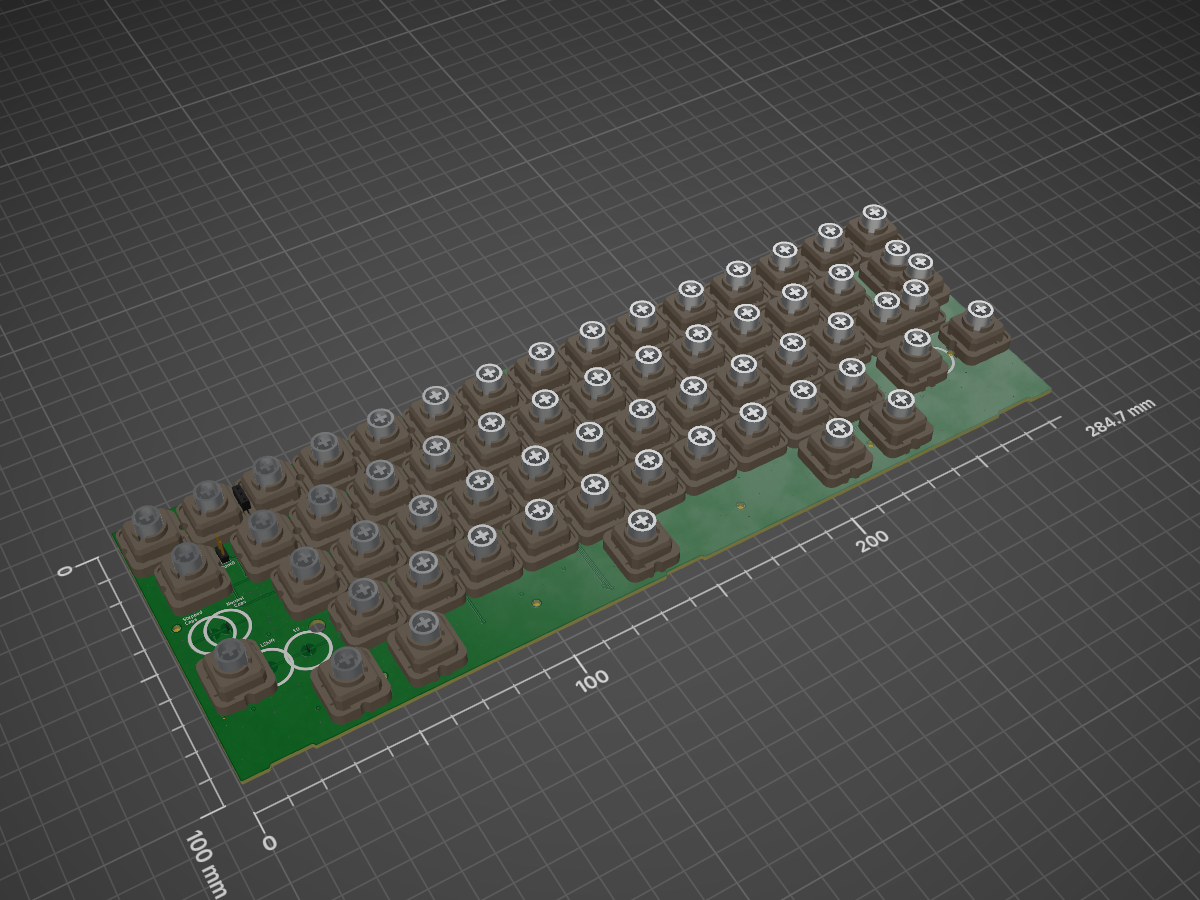
 4pplet/EC-Pro-23
Open source replacement PCB kit for the HHKB Pro 2 keyboard.
EC Pro2 Mainboard is an open-source printed circuit board by 4pplet, from the 4pplet/EC-Pro-2 repository on GitHub, published under the MIT licence. It is a 4-layer board of 284.7 × 100 mm with 138 parts on 65 nets, routed with 921 tracks and 638 vias.
It is built around the SN74AHCT1G125DBV, OPA350UA and 74HC4051, with the PRTR5V0U2X among its other parts. Its parts include 66 switches, 26 resistors, 13 capacitors, 6 ICs and 2 connectors. It belongs with the computers and single-board computers boards and the STM32 boards of this library.


Open source HHKB Pro2 Controller and mainboard.
This project is a continuation of my development of open source EC boards.
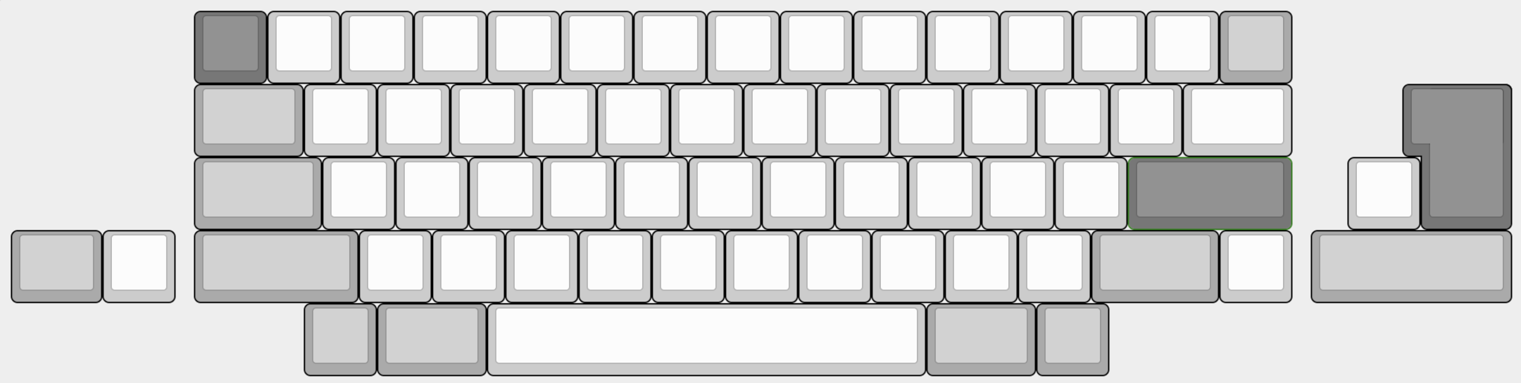
The supported layout options are the following:
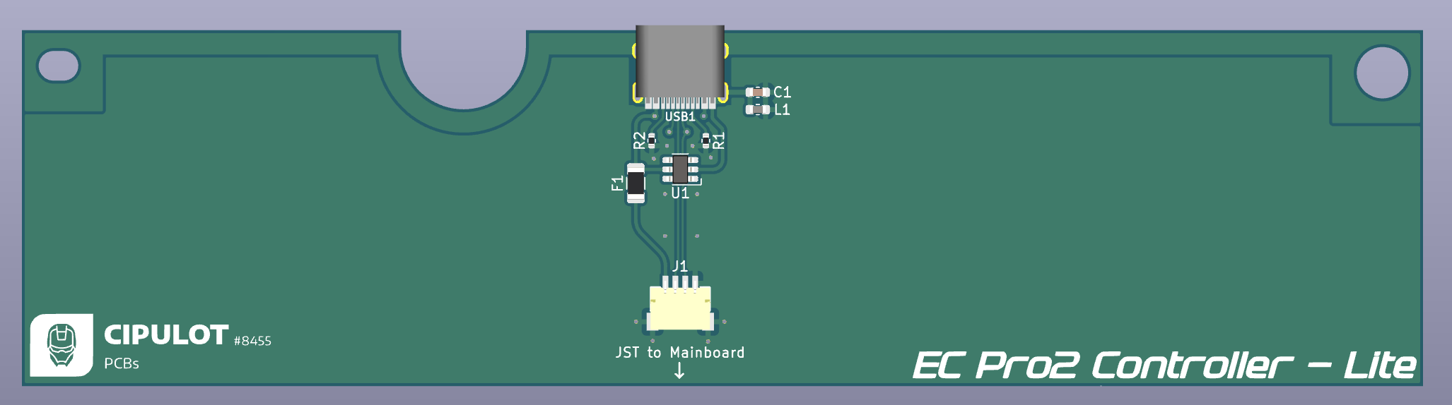
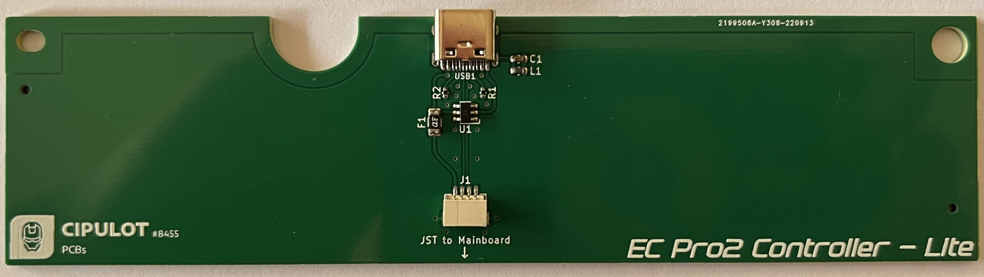
The Lite controller board is a slimmed down version of the controller board, featuring only protection hardware and a JST connector for the mainboard.
This is cost effective choice in case the user doesn't need the USB hub feature or the aftermarket case doesn't take advantage of it.
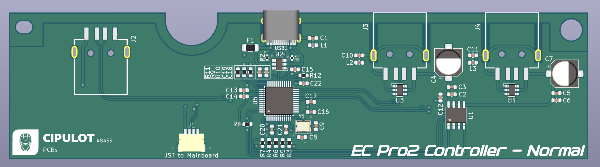
The Normal Controller instead is a full featured controller board, featuring a USB hub, a JST connector for the mainboard and a USB Type-C connector for the PC.
The USB hub is a USB 2.0 hub, featuring 3 USB-A 2.0 ports, one of which is internal, to be used for dongles or small USB drives.
Key features of the Normal Controller are:
NOTES
The internal USB port is intended only for low power devices, such as dongles and small usb drives as previously mentioned. It is not intended for high power devices. Furthermore it is not ESD protected nor current limited and shares the power rail with the rest of the controller.
The main USB-C port, as well as the 2x externally accessible USB-A downstream ports are ESD protected and current limited.
Keep in mind the the USB 2.0 power budget sets a typical current limit of 500mA, therefore that is the total budget available to the entire board (controller + mainboard + devices connected to the hub).
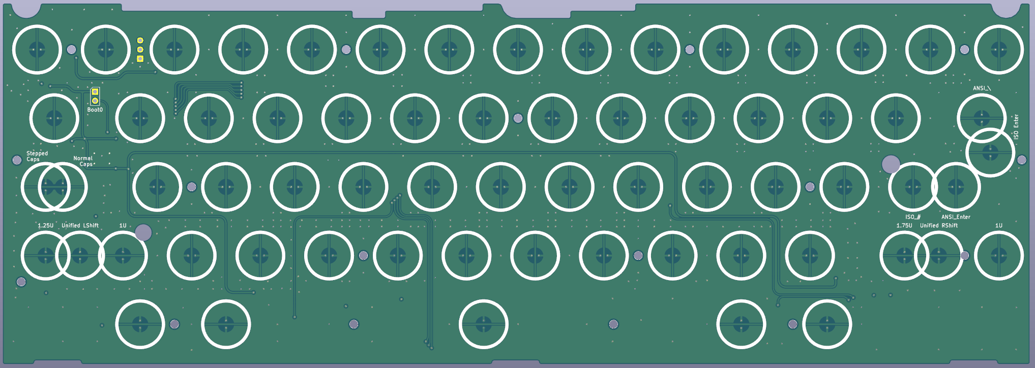
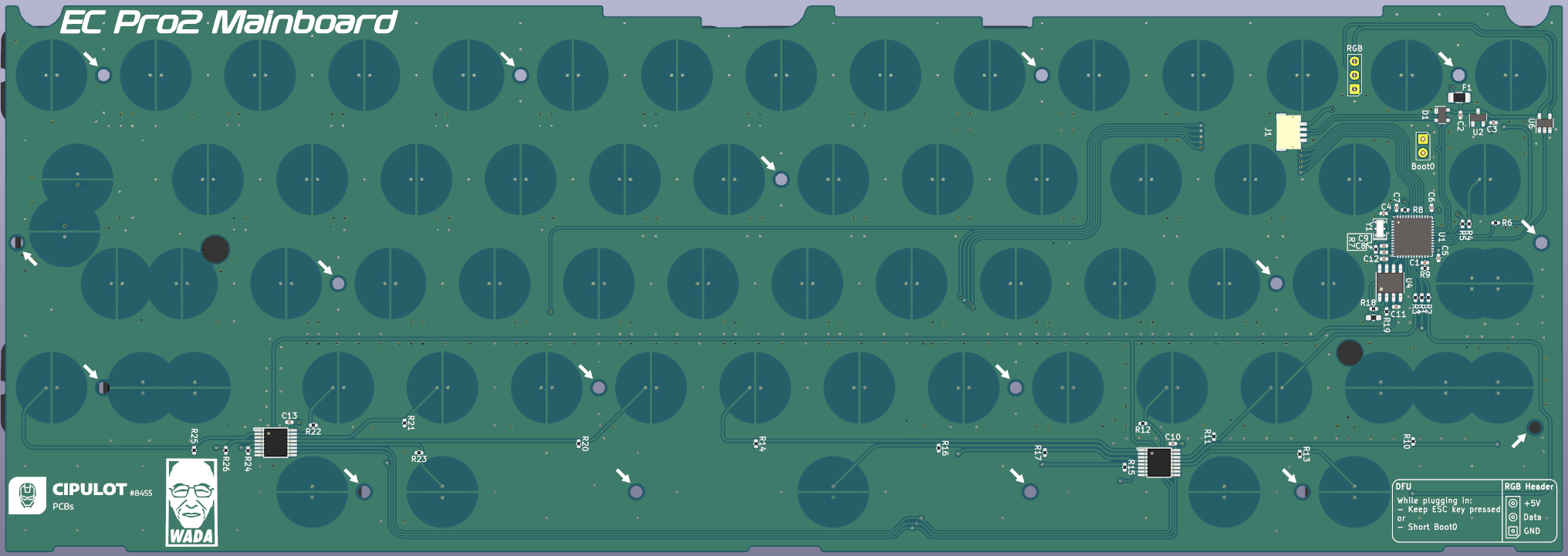
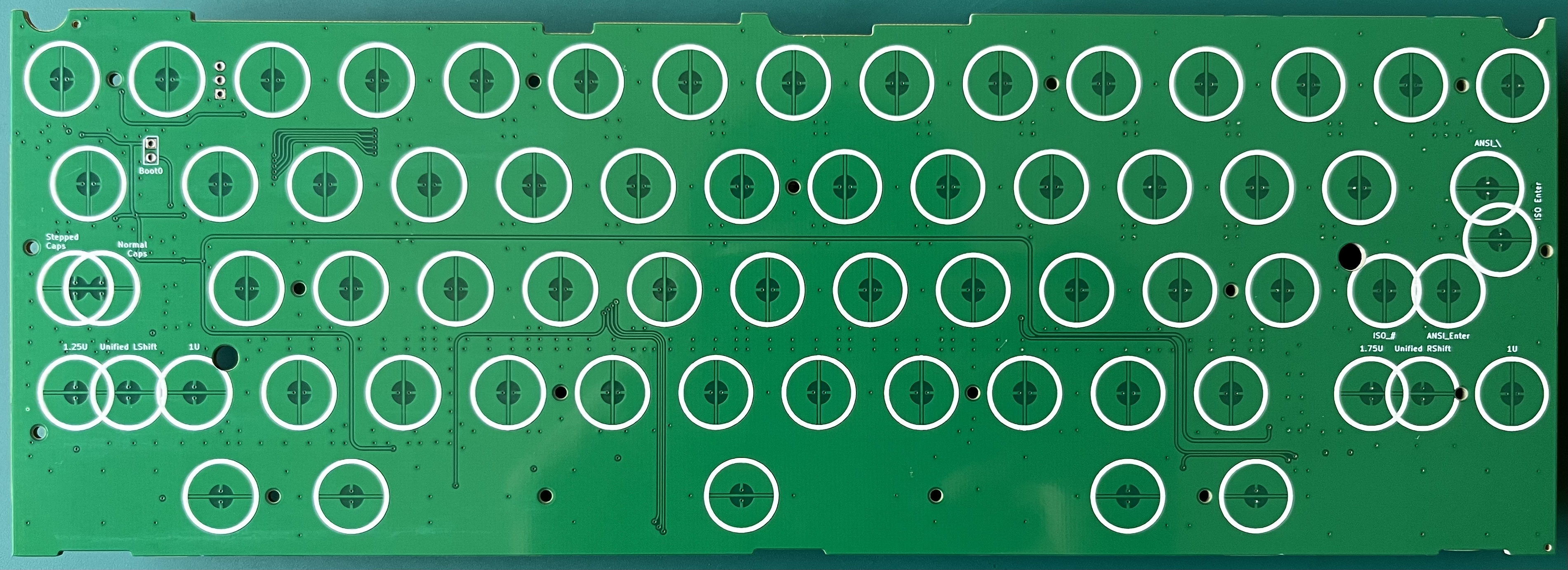
Mainboard:
Lite Controller board:
Normal Controller board:
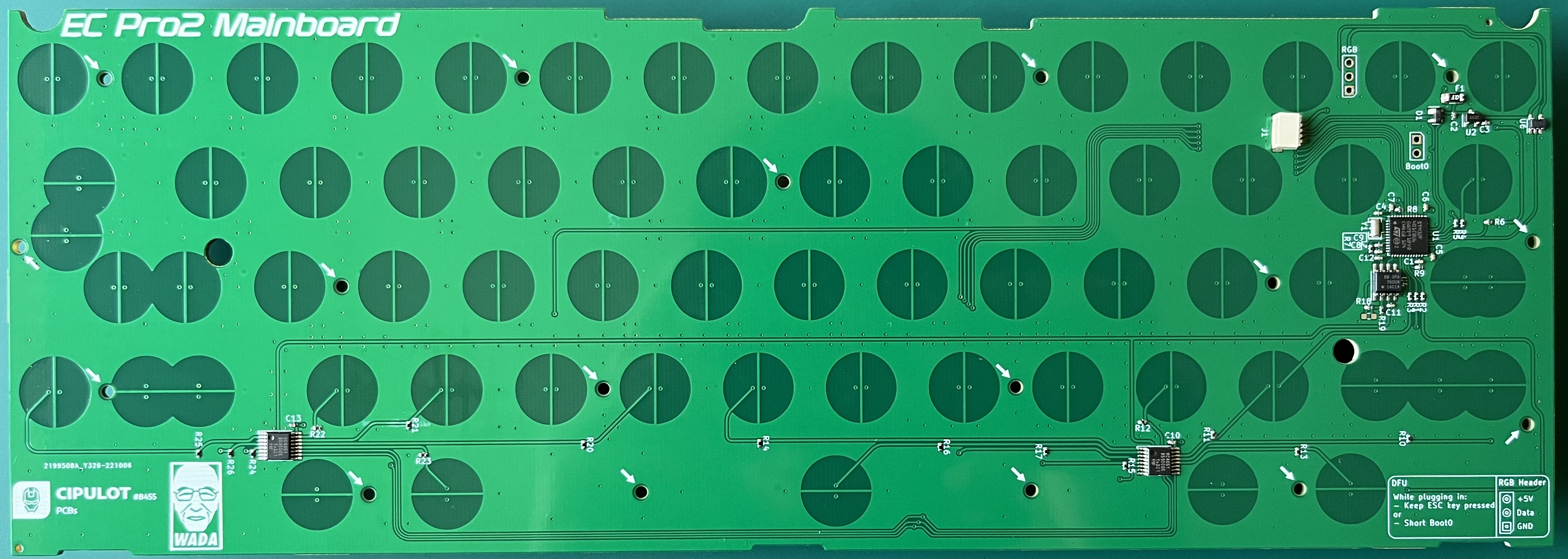
Mainboard:
Lite Controller:
Normal Controller:
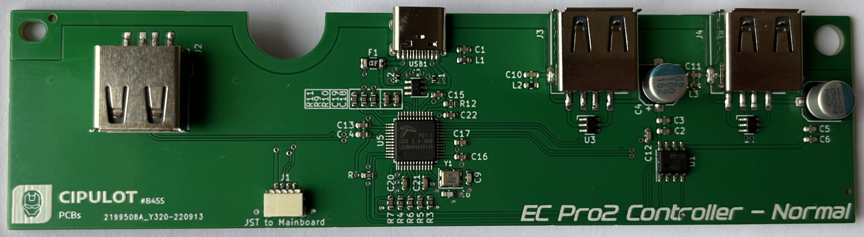
This revision implements all the main features of the mainboard ad controllers mentioned in the specifications.
The Revision 1 (Rev1) implements a USB hub based on the FE1.1 USB HUB IC.
Connection to the PC is achieved through a USB-C connector while devices downstream will use USB-A ports.
Mind that the USB-C connector is wider than the original USB mini connector used, therefore modifications to enlarge the port cutout on the case will be needed. In case you will use this board in an aftermarket case already designed with USB-C in mind n o further modifications are needed.
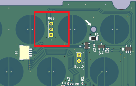
The mainboard features an RGB header for connecting +5V addressable RGB strips. THe properties of the lihting can be controlled through Vial or by assigning RGB control keycodes on the board itself.
On the bottom right corner of the PCB, near the bootloader instructions, a pinout diagram shows how to connect the strip to the header:

To access the DFU mode of the mainboard you can perform one of the following actions:
QK_BOOT keycode is assigned (if available)ESC (top left corner key) pressedBoot0 pins on the mainboard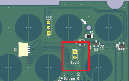
In order to have me highers compatibility possible with PCB manufacturers, I decided to design the board around the JLC7628 Stackup from JLCPCB.
The rational behind this is that the JCPCB stackup is relatively cheap and if the board worked with the stackup, it would be easier to get the board to work with pretty much any other many that offer an equivalent stackup and higher prices.
Both the Lite and Normal controllers can be instead be ordered with standard 2 layer stackup.
The production can be found in the Production folder.
As usual the *.zip files are the gerber files, BOM-*.csv are the BOM (Bill Of Material) files and POS-*.csv are the POS/CPL (Footprint POSition/Component Placement List) files.
As mentioned above, the mainboard is designed around the JLCPCB stackup. The mainboard is a 4 layer board.
Here are the options to select when ordering the mainboard:
EC_Pro2_Mainboard-F_Cu.gbrEC_Pro2_Mainboard-In1_Cu.gbrEC_Pro2_Mainboard-In2_Cu.gbrEC_Pro2_Mainboard-B_Cu.gbrFR-4 TG155All the other options can be left as default.
Here follows the options to be used for assembly:
Added by JLCPCByesOnce you upload the gerber files wait for the system to automatically recognize the board outline and layers. It will take a while, be patient.
PCB thickness has been tested on both 1.6mm and 1.2mm so it's your call on which one to use.
For Material Type I strongly suggest to use FR-4 TG155, using the standard FR4-Standard TG130-140 material might result in the board delamination and generally is not advised on 4 layer boards.
The EC Pro2 project is intended as a full replacement kit for the OEM HHKB Pro2 controller and main PCB. Therefore it IS NOT compatible with the OEM PCBs (both controller and mainboard).
This project is not endorse nor sponsored in any way by Topre Corporation and PFU Limited. The HHKB Logo and Topre logo are trademarks of their respective owners.
This project is released under the MIT License. For the license, please refer to the LICENSE.md file.
| Qty | Value | Footprint | References |
|---|---|---|---|
| 57 | EC_SW | cipulot_parts:ecs_pad_no_ring | SW2, SW10, SW11, SW12, SW13, SW14, SW15, SW16, SW17, SW18, SW19, SW20, SW21, SW22, SW23, SW24 +41 |
| 17 | 100k | Resistor_SMD:R_0402_1005Metric | R10, R11, R12, R13, R14, R15, R16, R17, R18, R20, R21, R22, R23, R24, R25, R26 +1 |
| 17 | MountingHole | cipulot_parts:HOLE_M2 | H1, H2, H3, H4, H5, H6, H7, H8, H10, H11, H12, H13, H14, H15, H16, H17 +1 |
| 8 | 100n | Capacitor_SMD:C_0402_1005Metric | C4, C5, C6, C7, C8, C10, C12, C13 |
| 5 | 100 | Resistor_SMD:R_0402_1005Metric | R1, R2, R3, R4, R6 |
| 3 | 10k | Resistor_SMD:R_0402_1005Metric | R7, R8, R9 |
| 3 | 1u | Capacitor_SMD:C_0402_1005Metric | C2, C3, C9 |
| 3 | EC_SW | cipulot_parts:ecs_pad_no_ring_1u_edge_cut | SW47, SW48, SW60 |
| 3 | LOGO | LOGO | G***, G***, G*** |
| 2 | 74HC4051 | cipulot_parts:TSSOP16 | U3, U5 |
| 1 | 1k | Resistor_SMD:R_0402_1005Metric | R19 |
| 1 | 220p | Capacitor_SMD:C_0402_1005Metric | C11 |
| 1 | 4.7u | Capacitor_SMD:C_0402_1005Metric | C1 |
| 1 | 500mA | Fuse:Fuse_1206_3216Metric | F1 |
| 1 | 8 MHz | Crystal:Resonator_SMD_Murata_CSTxExxV-3Pin_3.0x1.1mm | Y1 |
| 1 | ANSI_Enter | cipulot_parts:ecs_pad_no_ring | SW45 |
| 1 | ANSI_\ | cipulot_parts:ecs_pad_no_ring | SW30 |
| 1 | BOOT0 | Connector_PinHeader_2.54mm:PinHeader_1x02_P2.54mm_Vertical | SW1 |
| 1 | EC_SW | cipulot_parts:ecs_pad_no_ring_stepped&normal | SW32 |
| 1 | Ext_Res | Resistor_SMD:R_0603_1608Metric_Pad0.98x0.95mm_HandSolder | JP1 |
| 1 | ISO_Enter | cipulot_parts:ecs_pad_no_ring | SW31 |
| 1 | ISO_| | cipulot_parts:ecs_pad_no_ring | SW44 |
| 1 | JST | cipulot_parts:JST-SR-4 | J1 |
| 1 | OPA350 | Package_SO:SOIC-8_3.9x4.9mm_P1.27mm | U4 |
| 1 | PRTR5V0U2X | Package_TO_SOT_SMD:SOT-143 | D1 |
| 1 | RGB | Connector_PinSocket_2.54mm:PinSocket_1x03_P2.54mm_Vertical | J2 |
| 1 | SN74AHCT1G125 | Package_TO_SOT_SMD:SOT-23-5 | U6 |
| 1 | STM32F401CBUx | Package_DFN_QFN:QFN-48-1EP_7x7mm_P0.5mm_EP5.6x5.6mm | U1 |
| 1 | XC6206PxxxMR | Package_TO_SOT_SMD:SOT-23 | U2 |
The 137 most common of 138 parts.
4pplet/EC-Pro-2
Open source replacement PCB kit for the HHKB Pro 2 keyboard.

4pplet/EC-Pro-2
Open source replacement PCB kit for the HHKB Pro 2 keyboard.

4pplet/RF_R1_8-9Xu
Open source universal PCB for the Realforce R1 family of keyboards.


calvin-mcd/the-nicholas-van
EC (topre) PCB for trashman's vanagon

It measures 284.7 × 100 mm and has 4 copper layers, 1.59 mm thick.
138 parts, built around the SN74AHCT1G125DBV, OPA350UA, 74HC4051 and PRTR5V0U2X. The full list of its parts is on this page, with links to each part's symbol and footprint where PCBKit's library has them.
From the 4pplet/EC-Pro-2 repository on GitHub, at the commit this page was made from: the board is PCB/EC_Pro2_Mainboard/EC_Pro2_Mainboard.kicad_pcb and its schematic PCB/Controllers/EC_Pro2_Controller_Lite/EC_Pro2_Controller_Lite.kicad_sch. PCBKit opens the board in the browser, with nothing to install.
Its repository publishes it under the MIT licence: you may reuse it on that licence's terms (keep the author's notice, and for a copyleft licence share your changes alike).