
2 layers75 × 55 mm
Wellfed bench
Isaac-Duarte/wellfed
Open firmware that runs the PETLIBRO Granary PLAF103 pet feeder on your own Wi-Fi: no cloud, no account. Early and in testing.
93 parts8MIT
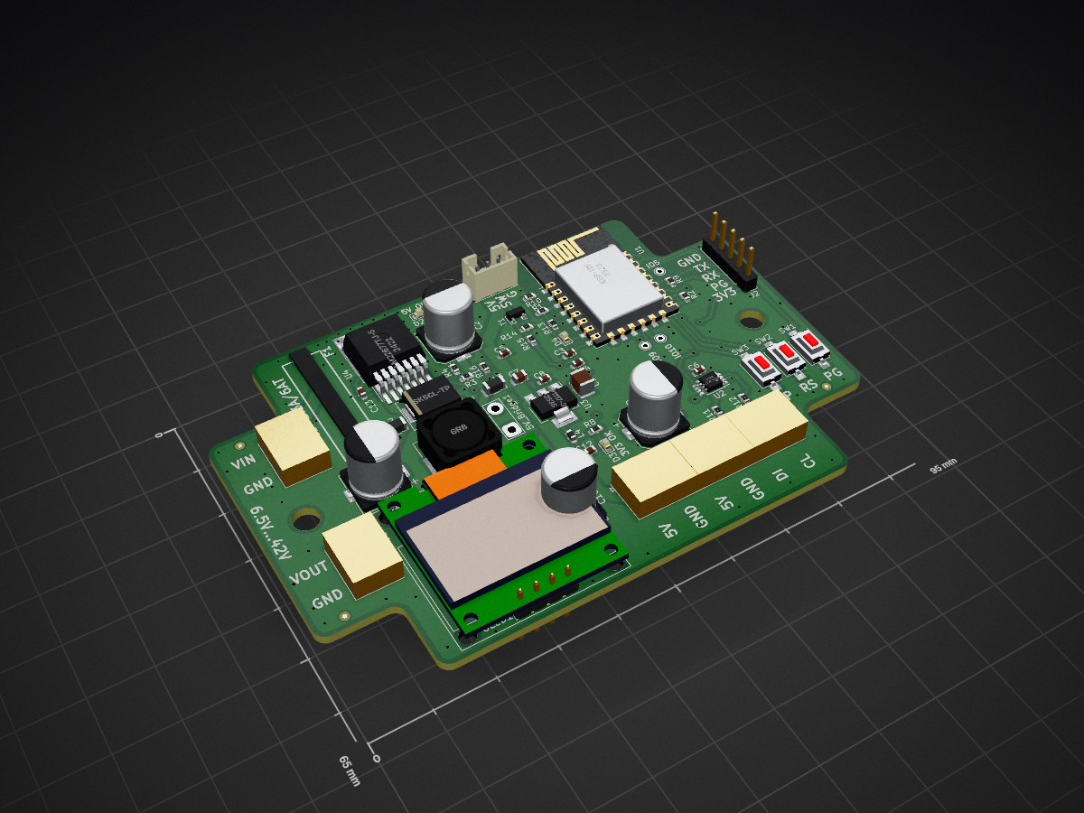
A small PCB with step-down for use with WLED firmware
Wled is an open-source printed circuit board by 3komma3volt, from the 3komma3volt/wled-controller repository on GitHub, published under the MIT licence. It is a 2-layer board of 95 × 65 mm with 64 parts on 42 nets, routed with 387 tracks and 180 vias.
It is built around the 74LVC2G125DP, ESP-12F and LM22677TJ-5.0, with the FDN337N and SK56L-TP among its other parts. Its parts include 16 resistors, 14 capacitors, 7 connectors, 4 ICs and 4 diodes. It belongs with the ESP8266 boards of this library.


A small ESP8266 controller with step-down for use with WLED firmware made with KICAD 6

This board was designed for a christmas lightshow and 17 of them were used. They were supplied from a central 24V power supply and the supply was chained from prop to prop. This made wireing very easy. The included 5V regulator supplies up to 5A which is pretty enough for some light props. The KICAD files include LCSC component numbers for direct ordering at JLCPCB The board shape is made for some cheap enclosures

First decide if you want to use the voltage regulator. In some cases, you need more power and then you can remove/not populate the U4 regulator and solder the 5V_Bridge1 on the board. Then the VIN supply must not more than 12V! With the brige, the voltage on the screw terminals is the same than VIN. So you could use 12V pixels whith this board or a powerful 5V supply. The ESP is supplied from an other voltage regulator. Without brige, the voltage regulator has to be mounted. Use following fusing for F1:
For programming an USB to UART converter is needed. Use following steps:
| Qty | Value | Footprint | References |
|---|---|---|---|
| 7 | 10k | Resistor_SMD:R_0603_1608Metric | R1, R2, R5, R7, R9, R10, R14 |
| 6 | 100n | Capacitor_SMD:C_0603_1608Metric | C3, C5, C6, C8, C12, C14 |
| 3 | 220u | Capacitor_SMD:CP_Elec_8x10 | C2, C10, C11 |
| 3 | Fiducial | Fiducial:Fiducial_0.75mm_Mask1.5mm | FID1, FID2, FID3 |
| 3 | LED | LED_SMD:LED_0603_1608Metric | D2, D3, D4 |
| 3 | SW_Push | Button_Switch_SMD:SW_SPST_CK_RS282G05A3 | SW1, SW2, SW3 |
| 3 | TestPoint | TestPoint:TestPoint_THTPad_D1.5mm_Drill0.7mm | TP3, TP4, TP7 |
| 2 | 10u | Capacitor_SMD:C_0805_2012Metric | C4, C7 |
| 2 | 1k | Resistor_SMD:R_0603_1608Metric | R6, R15 |
| 2 | 220 | Resistor_SMD:R_0603_1608Metric | R11, R12 |
| 2 | 30@100MHz | Inductor_SMD:L_1206_3216Metric | L2, L3 |
| 2 | 470 | Resistor_SMD:R_0603_1608Metric | R8, R13 |
| 2 | MountingHole | MountingHole:MountingHole_3.2mm_M3 | H1, H2 |
| 1 | 100u | Capacitor_SMD:C_1210_3225Metric | C9 |
| 1 | 10n/50V | Capacitor_SMD:C_0603_1608Metric | C13 |
| 1 | 220u/35V | Capacitor_SMD:CP_Elec_8x10 | C1 |
| 1 | 22@100MHz | Inductor_SMD:L_0603_1608Metric | L4 |
| 1 | 2k | Resistor_SMD:R_0603_1608Metric | R3 |
| 1 | 50k | Resistor_SMD:R_0603_1608Metric | R16 |
| 1 | 680 | Resistor_SMD:R_0603_1608Metric | R4 |
| 1 | 6A | FX0321:FX0321 | F1 |
| 1 | 6u8 | Inductor_SMD:L_10.4x10.4_H4.8 | L1 |
| 1 | 74LVC2G125 | Package_SO:TSSOP-8_3x3mm_P0.65mm | U2 |
| 1 | AP1117-33 | Package_TO_SOT_SMD:SOT-223-3_TabPin2 | U3 |
| 1 | Conn_01x03_Male | Connector_JST:JST_PH_B3B-PH-K_1x03_P2.00mm_Vertical | J3 |
| 1 | Conn_01x05_Male | Connector_PinHeader_2.54mm:PinHeader_1x05_P2.54mm_Vertical | J2 |
| 1 | ESP-12F | RF_Module:ESP-12E | U1 |
| 1 | FDN337N | Package_TO_SOT_SMD:SOT-23 | T1 |
| 1 | LED Injection | libs:OSTTC020162 | J5 |
| 1 | LED Strip Data | libs:OSTTC020162 | J7 |
| 1 | LED Strip Power | libs:OSTTC020162 | J4 |
| 1 | LM22677TJ-5 | Package_TO_SOT_SMD:TO-263-7_TabPin4 | U4 |
| 1 | Power IN | libs:OSTTC020162 | J1 |
| 1 | Power OUT | libs:OSTTC020162 | J6 |
| 1 | SK56L-TP | Diode_SMD:D_SMC | D1 |
| 1 | SSD1306 | SSD1306:128x64OLED | OLED1 |
| 1 | TestPoint_2Pole | TestPoint:TestPoint_2Pads_Pitch5.08mm_Drill1.3mm | 5V_Bridge1 |
It measures 95 × 65 mm and has 2 copper layers, 1.6 mm thick.
64 parts, built around the 74LVC2G125DP, ESP-12F, LM22677TJ-5.0 and FDN337N. The full list of its parts is on this page, with links to each part's symbol and footprint where PCBKit's library has them.
From the 3komma3volt/wled-controller repository on GitHub, at the commit this page was made from: the board is wled.kicad_pcb and its schematic wled.kicad_sch. PCBKit opens the board in the browser, with nothing to install.
Its repository publishes it under the MIT licence: you may reuse it on that licence's terms (keep the author's notice, and for a copyleft licence share your changes alike).
Isaac-Duarte/wellfed
Open firmware that runs the PETLIBRO Granary PLAF103 pet feeder on your own Wi-Fi: no cloud, no account. Early and in testing.

lipoyang/StackChanPwd
M5Stack-embedded super cute humanoid controller unit


vanvught/KiCad-GD32F427RE-LTC-SMPTE-no-PHY
KiCad GD32F427RE LTC-SMPTE no PHY


