4 layers123 × 81 mm
PortableRAM-8MB
2tf2294x4g-maker/MacintoshPortable8MB_RAM
Mac Portable Variable 4 or 8MB RAM expansion card — all-5V, AS6C8008 SRAM, ATF1502ASL CPLD. Expands to 9MB total (system max).
38 parts2CERN-OHL-S-2.0

 2tf2294x4g-maker/MacintoshPortable8MB_RAM_v32
Mac Portable Expansion Card with support for 2, 4, 6, or 8 MB and jumper for backlit or non backlit
PortableRAM-8MB is an open-source printed circuit board by 2tf2294x4g-maker, from the 2tf2294x4g-maker/MacintoshPortable8MB_RAM_v3 repository on GitHub, published under the CERN-OHL-S-2.0 licence. It is a 4-layer board of 123 × 81 mm with 63 parts on 159 nets, routed with 5,420 tracks and 424 vias.
It is built around the 74HC245D and AS6C8008-55ZIN. Its parts include 24 resistors, 19 capacitors, 11 ICs, 4 diodes and 3 connectors. It belongs with the FPGA and CPLD boards of this library.


Expands a Macintosh Portable to 9 MB total (1 MB onboard + 8 MB this card) — the maximum the Portable's address space supports.
All-5V design using 1M×8 SRAM chips and an ATF1502ASL CPLD. Works with both the M5120 (non-backlit) and M5126 (backlit) Portable via the MODEL jumper. Banks are added sequentially — no jumpers needed as you populate.
✅ VALIDATED ON REAL HARDWARE — 11 August 2026 Fully assembled and tested in an M5120 Macintosh Portable. All four banks populated and detected: 9 MB total confirmed in About This Macintosh. Memory benchmark scores 103 % of stock Portable speed with the J3 /DTACK wire fitted. Firmware rev 03.
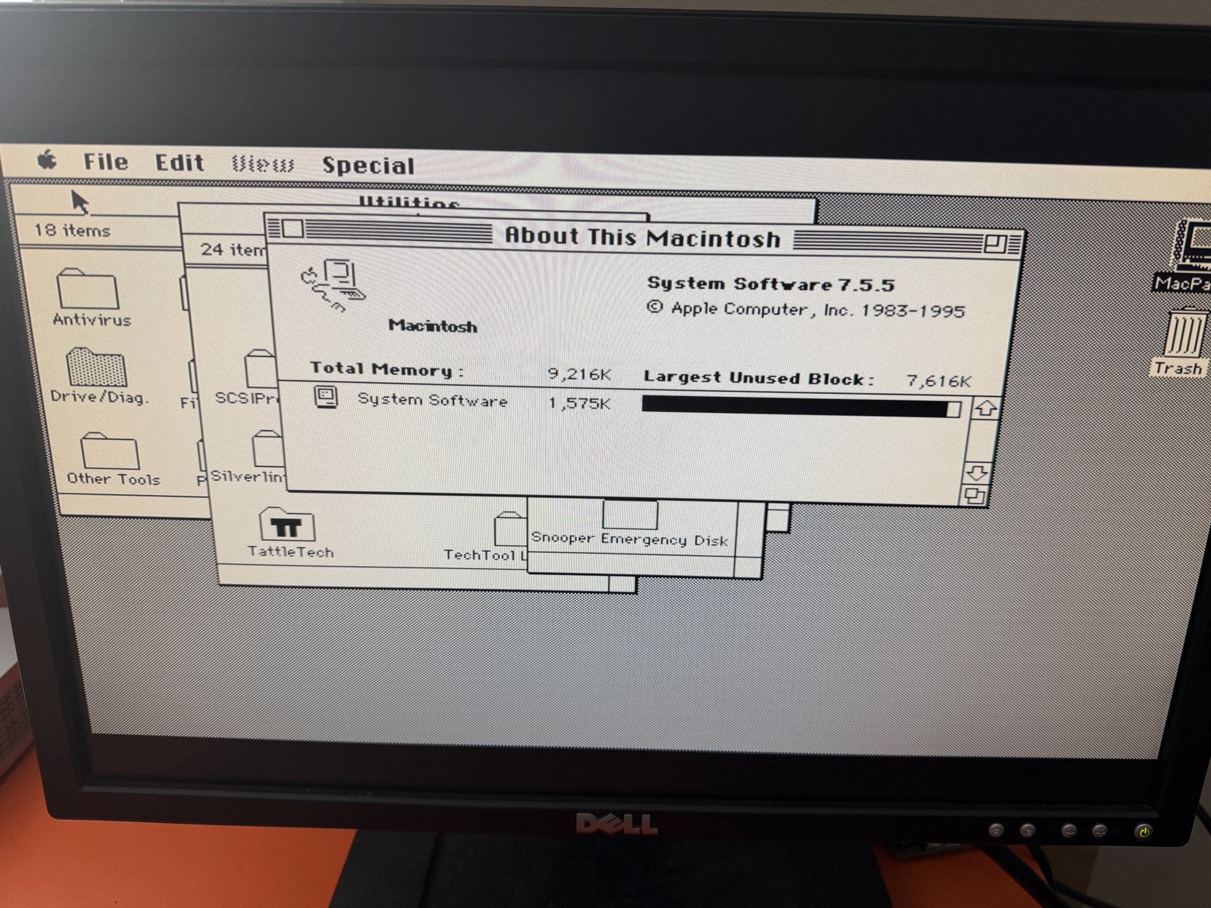
All 8 SRAMs populated — 9,216K total memory under System 7.5.5.
| v2 | v3 | |
|---|---|---|
| Model compatibility | M5120 only | M5120 + M5126 (MODEL jumper) |
| Bank indicator | none | 4 green activity LEDs (one per bank) |
| Ghost RAM protection | none | 10 KΩ pull-downs on SD0–SD15 |
| Population jumper | SIZE jumper (JP1) | none — sequential by design |
| DTACK output | bodge wire to CPLD pad | J3 header (pin 1 = /DTACK, pin 2 = /EXT_DTACK) |
| SRAM count | 8× AS6C8008 | 8× AS6C8008 (same chips) |
| Capacity | 8 MB (8× 1M×8 SRAM) |
| System total | 9 MB M5120 (open) / 7 MB M5126 (closed) |
| Bus width | 16-bit (two 8-bit SRAMs per bank) |
| Banks | 4 × 2 MB, populated sequentially |
| Logic | ATF1502ASL CPLD (5V, TQFP-44) |
| SRAM | 8× AS6C8008-55ZIN (5V, TSOP-II-44) |
| Layers | 4 (F.Cu signal / GND plane / +5V plane / B.Cu signal) |
| Connector | Samtec BCS-125-F-D-HE (50-pin 2×25, horizontal entry) |
| MODEL jumper | JP1: OPEN = M5120 non-backlit (9 MB) / CLOSED = M5126 backlit (7 MB) |
| Ref | Qty | Value | Package | Part / Notes |
|---|---|---|---|---|
| U1–U8 | 8 | AS6C8008-55ZIN | TSOP-II-44 | Alliance Memory — 1M×8 5V SRAM 55 ns. Order spares. |
| U9 | 1 | ATF1502ASL | TQFP-44 | Microchip ATF1502ASL-25AU44 — must be ASL (5V), not ASV |
| U10, U11 | 2 | 74HC245 | SOIC-20 wide | SN74HC245DW — verify wide (7.5 mm) body |
| J1 | 1 | RAM connector | Samtec BCS-125-F-D-HE | 50-pin socket, horizontal entry |
| J2 | 1 | JTAG header | 1×6 2.54 mm pin header | GND/VCC/TDO/TDI/TMS/TCK left-to-right |
| J3 | 1 | PDS DTACK header | 1×2 2.54 mm pin header | Pin 1 = /DTACK → PDS B7, Pin 2 = /EXT_DTACK → PDS B30 |
| JP1 | 1 | MODEL jumper | 1×2 2.54 mm pin header + shunt | OPEN = M5120 / CLOSED = M5126 |
| D1–D4 | 4 | Green LED | 0603 | Light while their bank is accessed — see Bank LEDs. Optional — safe to omit |
| R1–R4 | 4 | 330 Ω | 0402 | Series resistors for D1–D4 |
| R5–R20 | 16 | 10 KΩ | 0402 | Pull-downs on SD0–SD15 (SRAM side of 74HC245) — prevent ghost RAM |
| R21–R24 | 4 | 10 KΩ | 0805 | Pull-ups on CPLD unused inputs and MODEL jumper pin |
| C1–C14 | 14 | 100 nF | 0805 | X7R 50V ceramic bypass (one per IC) |
| C15–C19 | 5 | 10 µF | 0805 | X5R 16V ceramic bulk |
Full BOM: PortableRAM-8MB-v3-BOM.csv
The AS6C8008 (1M×8) and AS7C4096A (512K×8 used in the 4MB card) are both TSOP-II-44 but have different pinouts. Do not mix them between boards.
Banks are populated sequentially — each pair of SRAMs adds 2 MB. No jumpers required.
| Step | Chips | Total RAM |
|---|---|---|
| 1 | U1 + U5 | 2 MB |
| 2 | U2 + U6 | 4 MB |
| 3 | U3 + U7 | 6 MB |
| 4 | U4 + U8 | 8 MB |
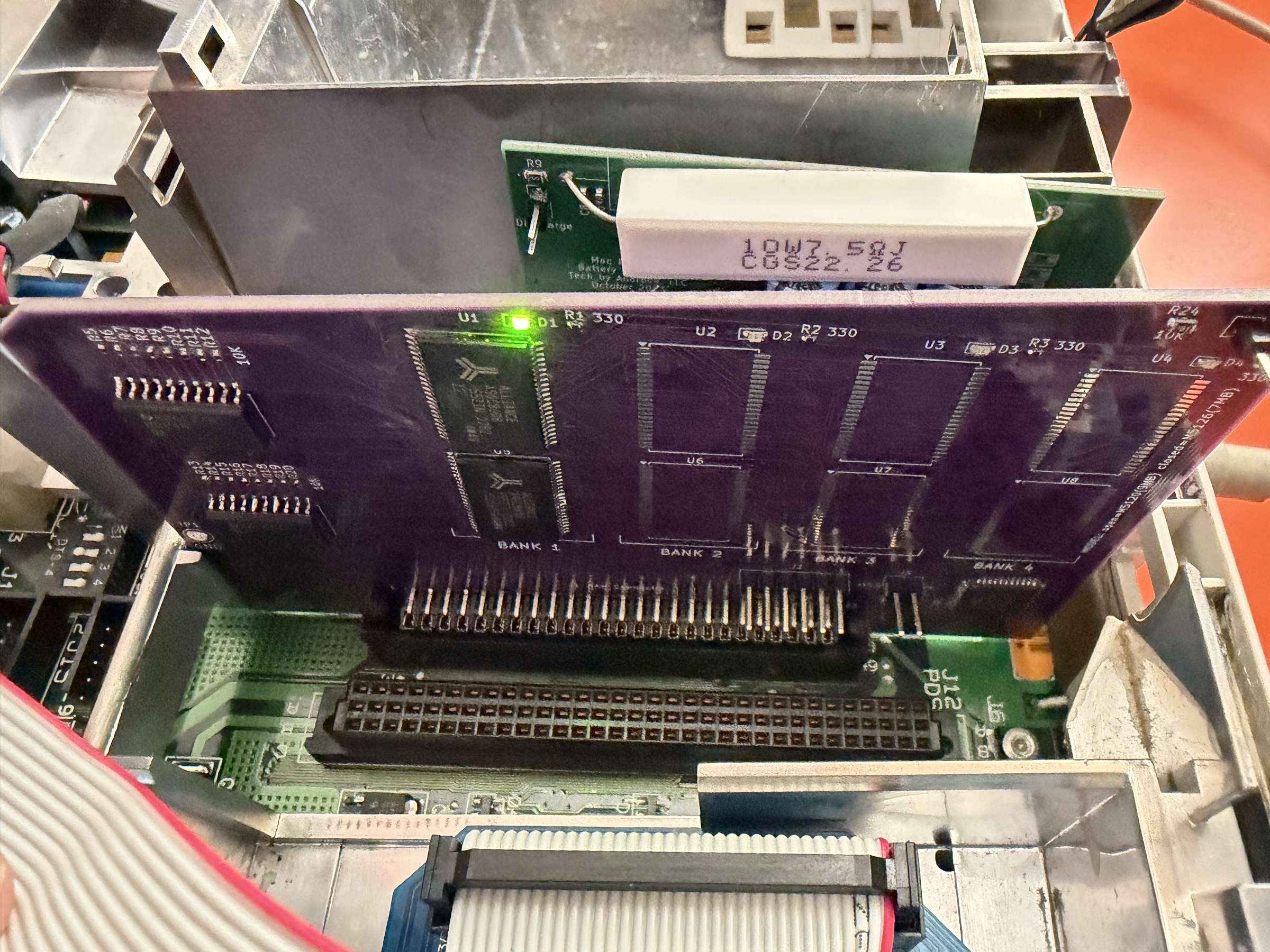
Card seated in the PDS slot with bank 1 only (U1 + U5) — 2 MB, D1 lit.
Each bank has a green LED (D1–D4) that lights while that bank is being accessed. A bank the OS is actively using glows steadily; a bank that is never touched after boot stays dark.
| LED | Bank | Chips |
|---|---|---|
| D1 | 1 | U1 + U5 |
| D2 | 2 | U2 + U6 |
| D3 | 3 | U3 + U7 |
| D4 | 4 | U4 + U8 |
Notes:
Firmware rev 02 latched each LED on the first access to its bank, intending "LED on = bank present". On real hardware all four lit regardless of how many banks were fitted. The Mac's boot memory sizing deliberately probes past the end of installed RAM to find the boundary, so every bank window gets addressed even when empty. The CPLD sits behind the 74HC245 transceivers and never sees the data bus, so it cannot tell a real response from the 0x0000 returned by the ghost-RAM pull-downs.
Rev 03 drops the latch and lights the LED while its bank is addressed:
LED0 = sel0 & strobe ;
LED1 = sel1 & strobe ;
LED2 = sel2 & strobe ;
LED3 = MODEL & sel3 & strobe ;
Populated banks are used continuously by the OS and glow; unpopulated banks flash once during the boot probe and then stay dark. Same information, no extra pins, and it frees all four flip-flops.
A true "populated" indicator would need data-bus sense — routing a few SD lines into the CPLD's input-only pins (37–40, otherwise unused) and latching only on a non-zero read. That is a future revision, not a v3 rework.
| JP1 | Portable model | System RAM |
|---|---|---|
| Open (no shunt) | M5120 non-backlit | 9 MB |
| Closed (shunt installed) | M5126 backlit | 7 MB |
The M5126 uses slot CS0 for its backlight controller, which conflicts with the top 2 MB bank. Closing JP1 disables that bank so the two don't fight. Leave open for M5120.
PortableRAM-8MB.kicad_pcb     — PCB layout (KiCad 9)
PortableRAM-8MB.kicad_sch     — Schematic
PortableRAM-8MB.kicad_pro     — Project file
PortableRAM.kicad_sym         — Custom symbol library
PortableRAM.pretty/           — Custom footprint library
Library.pretty/               — Additional footprints
Gerbers/                      — Gerber + drill files (ready to order)
PortableRAM-8MB-v3-Gerbers.zip — Same, zipped (upload directly to fab)
firmware/
  PortableRAM8_v3.pld            — CUPL source (ATF1502ASL logic)
  PortableRAM8_v3.jed            — Compiled JEDEC fusemap
  PortableRAM8_v3.svf            — SVF for OpenOCD programming
  PortableRAM8_v3.fit            — WinCUPL fit report
  program.sh                  — One-command programming script (Tigard)
  BUILD.md                    — Firmware build instructions (WinCUPL + Wine)
PortableRAM-8MB-v3-BOM.csvUpload PortableRAM-8MB-v3-Gerbers.zip to your preferred fab (JLCPCB, PCBWay, OSHPark, etc.).
Board settings:
Solder in this order:
The ATF1502ASL must be programmed before the card will work. Use J2 (1×6 header on the board edge).
| Pin | Signal |
|---|---|
| 1 | GND |
| 2 | VCC |
| 3 | TDO |
| 4 | TDI |
| 5 | TMS |
| 6 | TCK |
Set the Tigard voltage jumper to 5V before connecting.
cd firmware
./program.sh PortableRAM8_v3.svf
Success output ends with shutdown command invoked and no TDO mismatch errors.
See firmware/BUILD.md for the full build and programming pipeline (WinCUPL + Wine on Linux, prjbureau for SVF generation).
With a full build (all 8 SRAMs), you should see 9 MB in About This Macintosh (M5120) or 7 MB (M5126). All four green LEDs D1–D4 will show activity as the OS uses the banks.
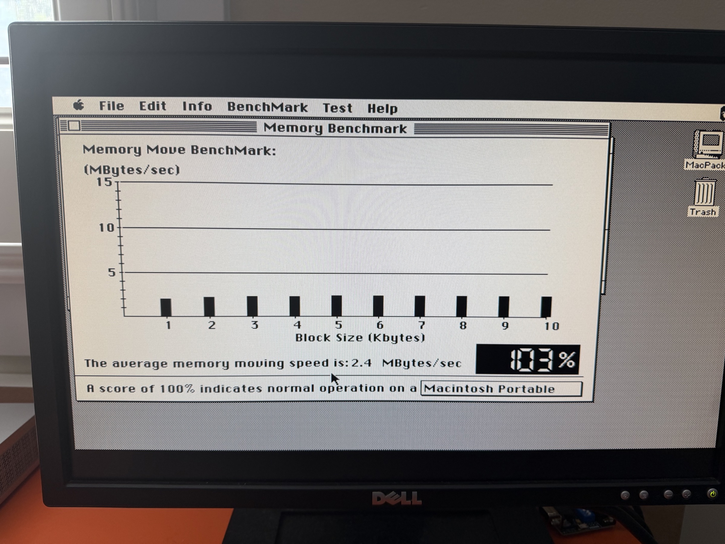
With the J3 /DTACK wire fitted, a full 8 MB build measures 2.4 MB/sec average memory move speed — 103 % of a stock Macintosh Portable. Expansion RAM therefore runs at full system speed, with no wait-state penalty on the upper banks.
The Mac Portable's GLU chip generates /DTACK for the 68000 with region-dependent timing:
| Address range | GLU /DTACK | Condition |
|---|---|---|
| 0x000000–0x4FFFFF | 2 clocks | Always — hardwired fast path |
| 0x500000–0x8FFFFF | 6 clocks | Normal operation (register configured) |
| 0x500000–0x8FFFFF | 18 clocks | After sleep/wake (register reset) |
The 8 MB card spans 0x100000–0x8FFFFF, straddling the split. Banks 0–1 (0x100000–0x4FFFFF) already get the GLU's 2-clock fast path. Banks 2–3 (0x500000–0x8FFFFF) run at 6 clocks and collapse to 18 clocks after sleep/wake when the GLU's DTACK register loses its configuration.
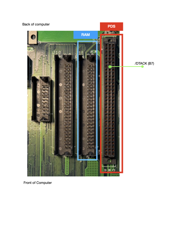
The fix is built into v3: the CPLD asserts /DTACK directly via J3 pin 1, bypassing the GLU for all card accesses. Connect a wire from J3 pin 1 to PDS slot pin B7 (/DTACK) on the Mac Portable motherboard. The CPLD's path is purely combinatorial — faster than even the GLU's 2-clock mode — and immune to sleep/wake state loss.
J3 pin 2 (/EXT_DTACK → PDS B30) is an optional second output for experimentation.
Validated on v2 hardware (July 2026):
| Configuration | Speedometer | Snooper | Post-sleep |
|---|---|---|---|
| 1 MB card (baseline) | 1.990 | 87% | 1.985 |
| 8 MB card — no DTACK fix | 1.486 | 51% | 0.974 / 22% |
| 8 MB card + CPLD DTACK | 2.170 | 102% | 2.170 |
| 4 MB card + CPLD DTACK | 2.170 | 102% | 2.170 |
The CPLD outperforms the GLU's fastest mode (102% vs 87% baseline) because its combinatorial propagation delay is well under one bus clock. Post-sleep collapse is fully eliminated. The 4 MB result confirms the CPLD path is faster than even the GLU's hardwired 2-clock mode — the fix benefits all bank configurations, not just the upper 8 MB range.
The PDS connector is the 96-pin DIN-41612 on the Mac Portable motherboard (3 rows A/B/C, 32 pins each). Pin B7 is in row B, position 7 from the component side.
Bare PCB (JLCPCB, purple soldermask, ENIG, 1.6 mm)
| Top | Bottom |
|---|---|
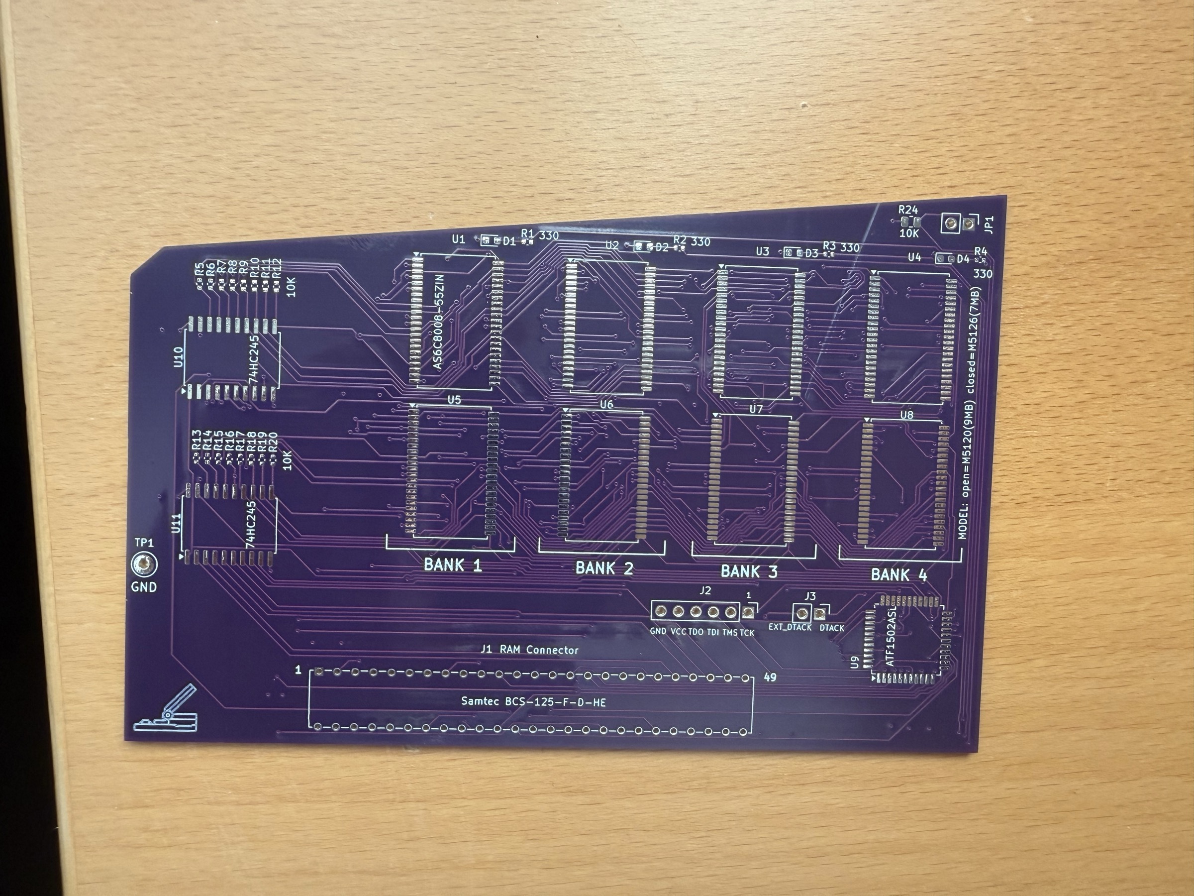 | 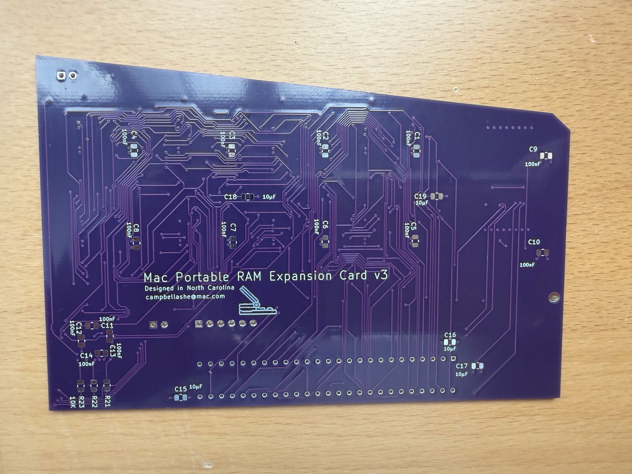 |
Fully populated — all 8 SRAMs, CPLD, transceivers, passives and connectors
| Top | Bottom |
|---|---|
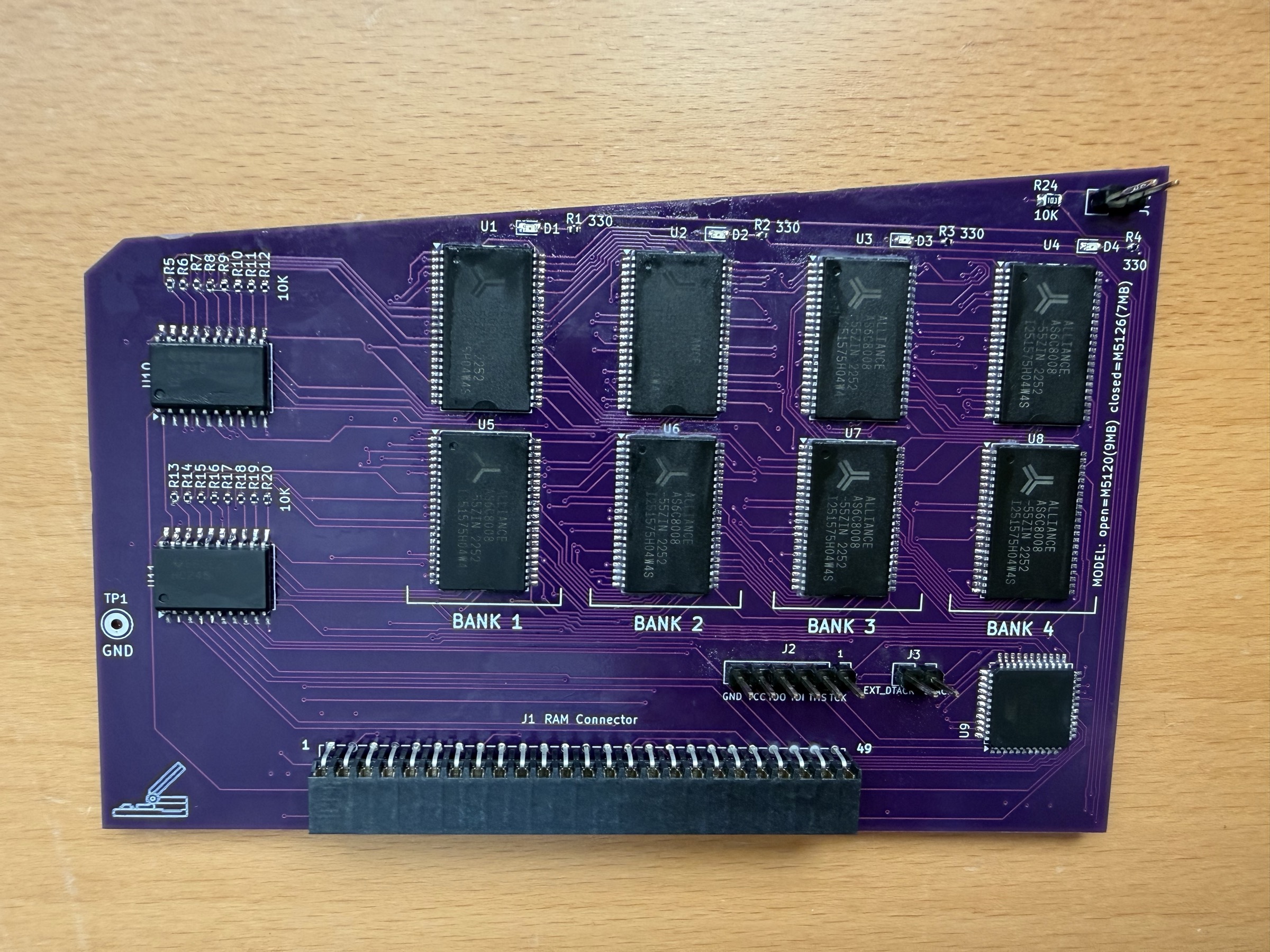 | 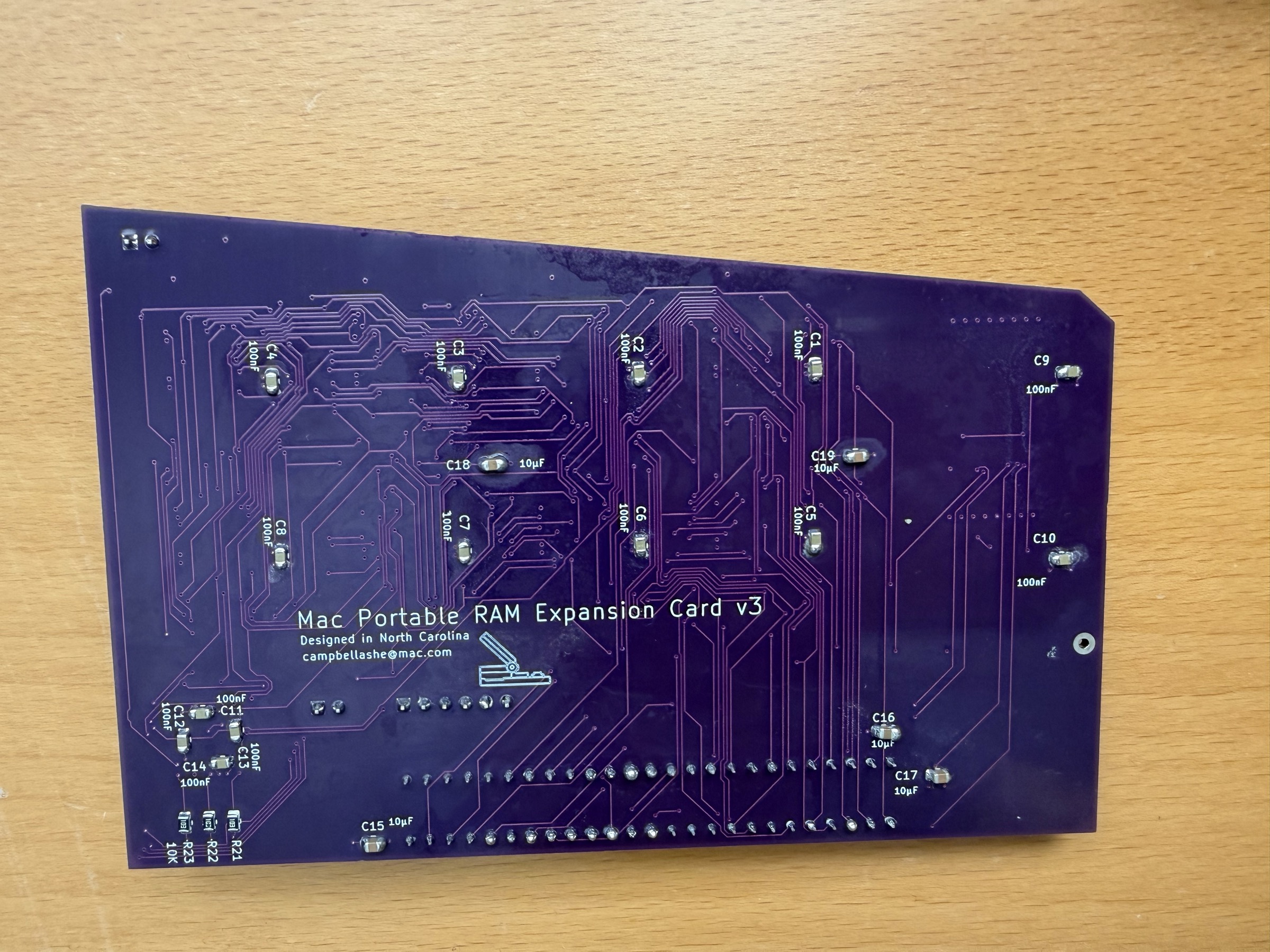 |
| Rev | Date | Change |
|---|---|---|
| 01 | 2026-07-18 | Initial v3 firmware. Fixed LED1–LED3 assigned to pins 37/38/39 (dedicated input-only macrocells — the fitter silently fell back to IGNORE and scrambled every pin). Moved to 42/43/44. |
| 02 | 2026-07-27 | DTACK → pin 23, EXT_DTACK → pin 31. Registered latching LEDs. |
| 03 | 2026-08-11 | Current. LEDs changed from registered latches to combinatorial activity indicators — see Bank LEDs. Pin assignments unchanged; 0 flip-flops used (was 4); macrocells 27 → 23. Validated on hardware. |
⚠️ Pins 37–41 on the ATF1502ASL TQFP-44 are always input-only. Never declare an output there — the fitter abandons
PREASSIGN=KEEPand reassigns every pin.
Dynamic Engineering Mac Portable RAM Card
The address decode and bus control logic in PortableRAM8_v3.pld is derived from GAL22V10 PLD source files originally written for the Dynamic Engineering commercial RAM expansion card. These files define the core signal equations — bank chip-select generation, byte-lane write control via UDS*/LDS*, bus transceiver direction, and output enable timing. The original .PLD files were recovered and shared by techknight on the TinkerDifferent forum and #skunkworks Discord. Translated here from three GAL22V10 chips to a single ATF1502ASL CPLD, with corrections to the r_w_u equation and address decode base, and extended for 8MB capacity and M5126 compatibility.
miejas — Macintosh Portable 4MB Memory Expansion https://github.com/miejas/Macintosh-Portable-4-MB-Memory-Expansion Open-source 4MB RAM card used as a cross-reference for connector pinout, bus transceiver approach, and firmware structure.
Reza Fouladian — PortableRAM BGA 8MB https://github.com/rezafouladian/PortableRAM-BGA-8MB BGA-format 8MB card using the ATF1502ASV (3.3V CPLD) and SN74LVC4245A level translators. Reference for the 8MB address decode strategy and CPLD pin planning. Reza also provided direct guidance on driving /DTACK from the CPLD and on the Mac Portable PDS connector pinout — specifically confirming that /DTACK is available on PDS pin B7 and can be driven directly from a CPLD output. This insight is the basis for the J3 DTACK header on v3 and the validated bodge fix on v2.
Apple Mac Portable Developer Notes & Schematics Apple's original hardware documentation for the Mac Portable expansion bus, memory map, and GLU register behaviour (including the $FC0200 DTACK register).
CERN-OHL-S-2.0PortableRAM8_v3.pld) — MIT · SPDX MITBoth licence texts are included in full in this repository. Do what you like — just share improvements.
| Qty | Value | Footprint | References |
|---|---|---|---|
| 16 | 10K | Resistor_SMD:R_0402_1005Metric | R5, R6, R7, R8, R9, R10, R11, R12, R13, R14, R15, R16, R17, R18, R19, R20 |
| 14 | 100nF | Capacitor_SMD:C_0805_2012Metric | C1, C2, C3, C4, C5, C6, C7, C8, C9, C10, C11, C12, C13, C14 |
| 8 | AS6C8008-55ZIN | Package_SO:TSOP-II-44_10.16x18.41mm_P0.8mm | U1, U2, U3, U4, U5, U6, U7, U8 |
| 5 | 10µF | Capacitor_SMD:C_0805_2012Metric | C15, C16, C17, C18, C19 |
| 4 | 10K | Resistor_SMD:R_0805_2012Metric | R21, R22, R23, R24 |
| 4 | 330 | Resistor_SMD:R_0402_1005Metric | R1, R2, R3, R4 |
| 4 | GREEN | LED_SMD:LED_0603_1608Metric | D1, D2, D3, D4 |
| 2 | 74HC245 | Package_SO:SOIC-20W_7.5x12.8mm_P1.27mm | U10, U11 |
| 1 | ATF1502ASL | Package_QFP:TQFP-44_10x10mm_P0.8mm | U9 |
| 1 | GND | TestPoint_GND | TP1 |
| 1 | JTAG_Header_2.54mm_1x06 | Connector_PinHeader_2.54mm:PinHeader_1x06_P2.54mm_Vertical | J2 |
| 1 | MODEL: open=M5120(9MB) closed=M5126(7MB) | Connector_PinHeader_2.54mm:PinHeader_1x02_P2.54mm_Vertical | JP1 |
| 1 | PDS Header 1x2 | Connector_PinHeader_2.54mm:PinHeader_1x02_P2.54mm_Vertical | J3 |
| 1 | RAM Connector | PortableRAM:Samtec_BCS-125-F-D-HE | J1 |
2tf2294x4g-maker/MacintoshPortable8MB_RAM
Mac Portable Variable 4 or 8MB RAM expansion card — all-5V, AS6C8008 SRAM, ATF1502ASL CPLD. Expands to 9MB total (system max).

number42net/pcmcia-sram
This board is primarily designed for use in the Amstrad NC-100 and NC-200 portable computers, but will likely work in other computers as well.


slu4coder/Minimal-64x4-Home-Computer
My DIY TTL home computer with VGA and PS/2 and 4x the processing power of a Commodore C64 or Apple II.

slu4coder/Minimal-UART-Computer-1-2
Legacy: Version 1 and 2 of my TTL-only CPU featuring UART I/O, an expansion port, 512KB SSD at up to 10MHz clock speed

crmaykish/mackerel-68k
A series of single-board Motorola 68k computers with support for modern Linux
It measures 123 × 81 mm and has 4 copper layers, 1.63 mm thick.
63 parts, built around the 74HC245D and AS6C8008-55ZIN. The full list of its parts is on this page, with links to each part's symbol and footprint where PCBKit's library has them.
From the 2tf2294x4g-maker/MacintoshPortable8MB_RAM_v3 repository on GitHub, at the commit this page was made from: the board is PortableRAM-8MB.kicad_pcb and its schematic PortableRAM-8MB.kicad_sch. PCBKit opens the board in the browser, with nothing to install.
Its repository publishes it under the CERN-OHL-S-2.0 licence: you may reuse it on that licence's terms (keep the author's notice, and for a copyleft licence share your changes alike).