2 layers36.1 × 21 mm

 123swk123/uart_data_logger1
UART data logger to SD card using CH32V003
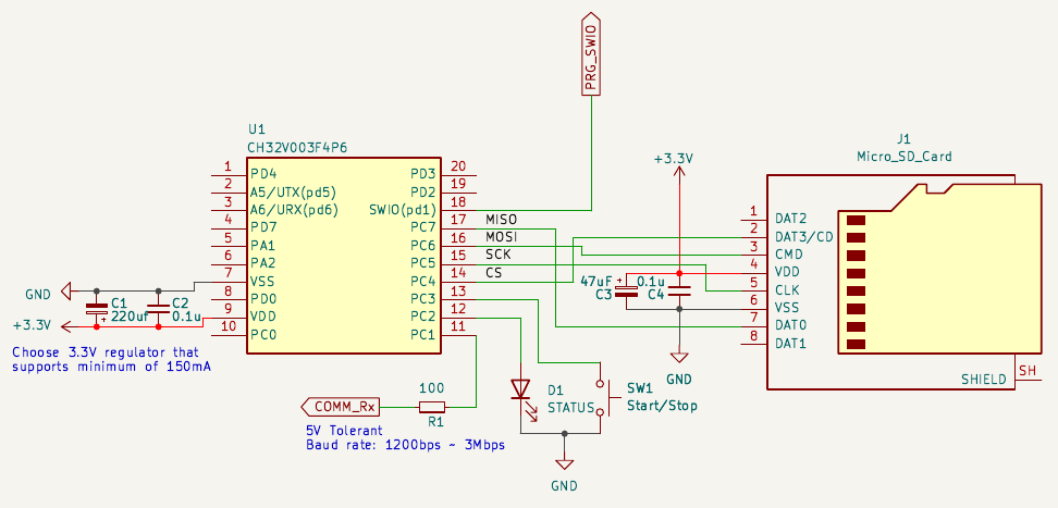
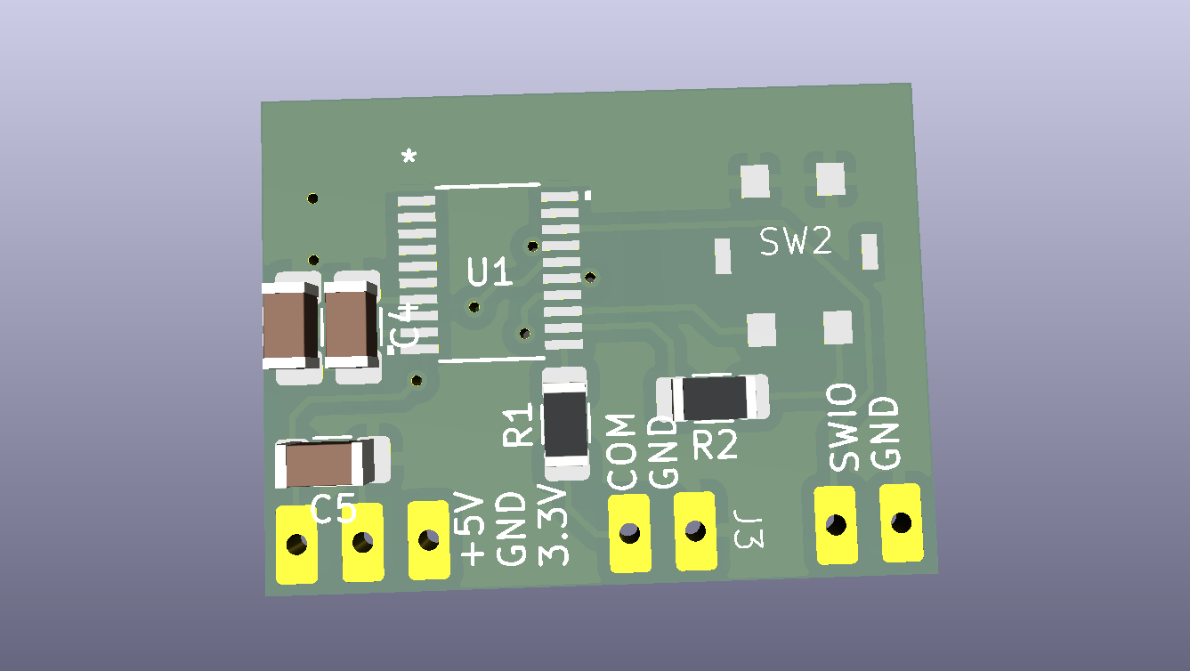
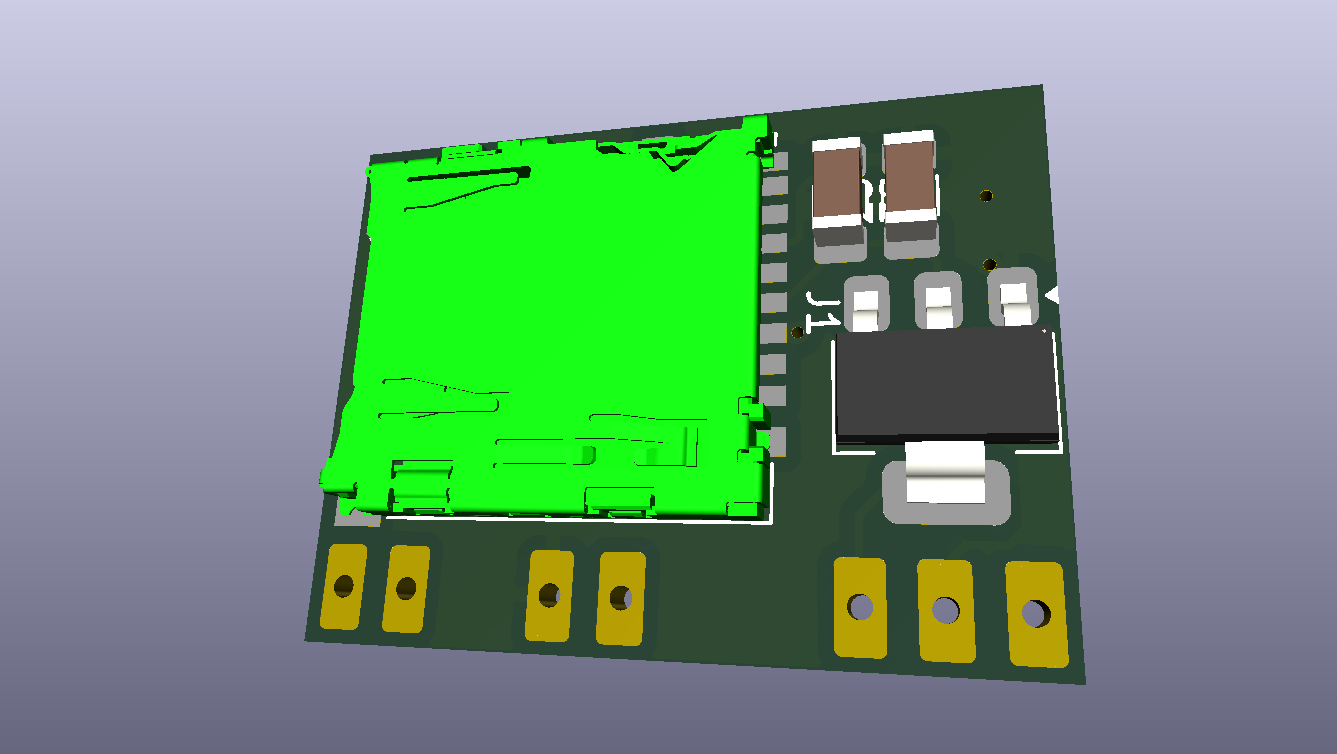
Uart data logger is an open-source printed circuit board by 123swk123, from the 123swk123/uart_data_logger repository on GitHub, published under the MIT licence. It is a 2-layer board of 25.9 × 19.3 mm with 14 parts on 29 nets, routed with 98 tracks and 8 vias.
It is built around the CH32V003F4P6 and AZ1117CH-3.3TRG1. Its parts include 5 capacitors, 4 connectors, 2 resistors, 2 ICs and 1 switch. It belongs with the interfaces and adapters and sensors and measurement boards and the RISC-V boards of this library.


[!NOTE] Work in progress...
This is a simple UART data logger, logger saves the data to FAT(12/16/32) formatted SD card.
| Status LED | Remarks |
|---|---|
| OFF | Logger stopped, free to remove the SD card after powering down |
| ON | Logger running, do not remove the card |
| Constant blinking | Logger error |
| Brief pulsing | Actively logging the received UART data |
first 2 lines are comment and they are skipped during the configuration process
3rd line describes the serial port configuration.
s<no>:baud rate,data bits<8,9>,parity<0,1,2>,stop bits<1,2>,output formatter<c,d,x,X>,seq start char,seq end char
s<no>:    Serial port number, starting from 1
range:    1 to Maximum no.of UART HW supported by the controller, in case of CH32V003 its just 1.
Example: s1baud rate: UART logger baud rate
range: 1200 ~ 300000 (check CH32v003 reference manual to calculate the percentage error due to divider round off)
Example: 115200data bits: UART logger data bits per frame
range: 8, 9
Example: 8parity: UART data partiy enable/disable
range: 0 - No parity (disabled)
1 - odd parity
2 - even parity
Example: 0stop bits: No.of stop bits per frame
range: 1, 2
Example: 1output formatter: logger output encode format
range: c - store the UART data in a transparent 8-bit ASCII raw
u - store the UART data as unsigned decimal value
x - store the UART data as hexadecimal value
X - store the UART data as hexadecimal value (all caps)
Example: xseq start char: a 9-bit unsigned integer. Upon reciving this character logger notes the event time stamp at start of the row/line
and the logger continues to log the sub-sequent received data in the same row/line as per the output format
Note: This seq start character will not be logged.
time stamp format: hour.minute.seconds.milli second (resolution: 100milli)
range: 0 ~ 511
Example: 13 (\r)seq stop char: a 9-bit unsigned integer. Upon reciving this character logger closes the current row/line with \r\n and
creates a new row/line, then the logger waits for seq start character.
Note: seq stop character will not be logged; Seq start and stop char can be the same.
range: 0 ~ 511
Example: 10 (\n)4th line describes the time offset information.
t:year,month,day,hour,minute
t:  start of time offset definition

year:     unsigned 16bit integer
range:    > 1980
Example:  2026

month:    unsigned 16bit integer
range:    1 ~ 12
Example:  2

day:      unsigned 16bit integer
range:    1 ~ 31
Example:  10

hour:     unsigned 16bit integer
range:    0 ~ 23
Example:  22

minute:   unsigned 16bit integer
range:    0 ~ 59
Example: 0[!WARNING] Not all aspects of the functionality was tested (This was a side project)
c - ASCII charactersu - unsigned decimalx/X - Hexadecimal\r0xFF0x1CC| Qty | Value | Footprint | References |
|---|---|---|---|
| 2 | 0.1u | Capacitor_SMD:C_1206_3216Metric_Pad1.33x1.80mm_HandSolder | C2, C4 |
| 2 | Conn_01x02 | swk:1x02_THT_P2.54mm | J3, J4 |
| 1 | 100 | Resistor_SMD:R_1206_3216Metric_Pad1.30x1.75mm_HandSolder | R1 |
| 1 | 100uF | Capacitor_SMD:C_1206_3216Metric_Pad1.33x1.80mm_HandSolder | C1 |
| 1 | 10uF | Capacitor_SMD:C_1206_3216Metric_Pad1.33x1.80mm_HandSolder | C5 |
| 1 | 1k | Resistor_SMD:R_1206_3216Metric_Pad1.30x1.75mm_HandSolder | R2 |
| 1 | 47uF | Capacitor_SMD:C_1206_3216Metric_Pad1.33x1.80mm_HandSolder | C3 |
| 1 | AZ1117CH-3.3TRG1 | Package_TO_SOT_SMD:SOT-223-3_TabPin2 | U3 |
| 1 | CH32V003F4P6 | swk:TSSOP20 | U1 |
| 1 | Conn_01x03 | swk:1x03_THT_P2.54mm | J2 |
| 1 | Micro_SD_Card | Connector_Card:microSD_HC_Hirose_DM3AT-SF-PEJM5 | J1 |
| 1 | SW_Push_LED | swk:SW_Push_LED_AK104238 | SW2 |
It measures 25.9 × 19.3 mm and has 2 copper layers, 1.6 mm thick.
14 parts, built around the CH32V003F4P6 and AZ1117CH-3.3TRG1. The full list of its parts is on this page, with links to each part's symbol and footprint where PCBKit's library has them.
From the 123swk123/uart_data_logger repository on GitHub, at the commit this page was made from: the board is schematics/uart_data_logger.kicad_pcb and its schematic schematics/uart_data_logger.kicad_sch. PCBKit opens the board in the browser, with nothing to install.
Its repository publishes it under the MIT licence: you may reuse it on that licence's terms (keep the author's notice, and for a copyleft licence share your changes alike).


gili-yankovitch/SwordOfSecrets
To solve the challenge you will need to discover a series of flags, hidden inside the sword. Each one will help you unlock the next step in the challenge, to finally reveal the ultimate secret the sword holds.


dwillmore/TSSOP20_breakout
A generic breakout board for TSSOP20 chips to a SIP header meant for breadboard use

bsidestlv/bsidestlv-2025-badge
To solve the challenge you will need to discover a series of flags, hidden inside the badge. Each one will help you unlock the next step in the challenge, to finally reveal the ultimate secret the badge holds.


bsidesorlando/2026-badge
The electronic badge for BSides Orlando 2026, themed around retro-futurism: a 1960s World's Fair vision of tomorrow, with Lil Chompy the alligator at the wheel of a flying car.