Blog ·
The whole ATmega328P
Sergey Alekseev
When the lab ran only our own small C programs, the ATmega328P model had to be as big as those
programs, which was not very big. Then real Arduino sketches
arrived with real libraries and libraries touch everything: Servo reprograms Timer1, the core’s
millis() lives in Timer0’s overflow interrupt, analogWrite() uses all three timers, Wire drives
the TWI with interrupts, Adafruit’s SSD1306 library keeps a 1 KB frame buffer and sends it over I²C. A
model that knows “the common registers” breaks on the first sketch from the internet.
So the model is now the whole chip at its registers, written from the data sheet (DS40002061B),
in crates/pcbkit-lab/src/avr. The same code is the ATmega168P with its own flash, RAM, EEPROM and
signature.
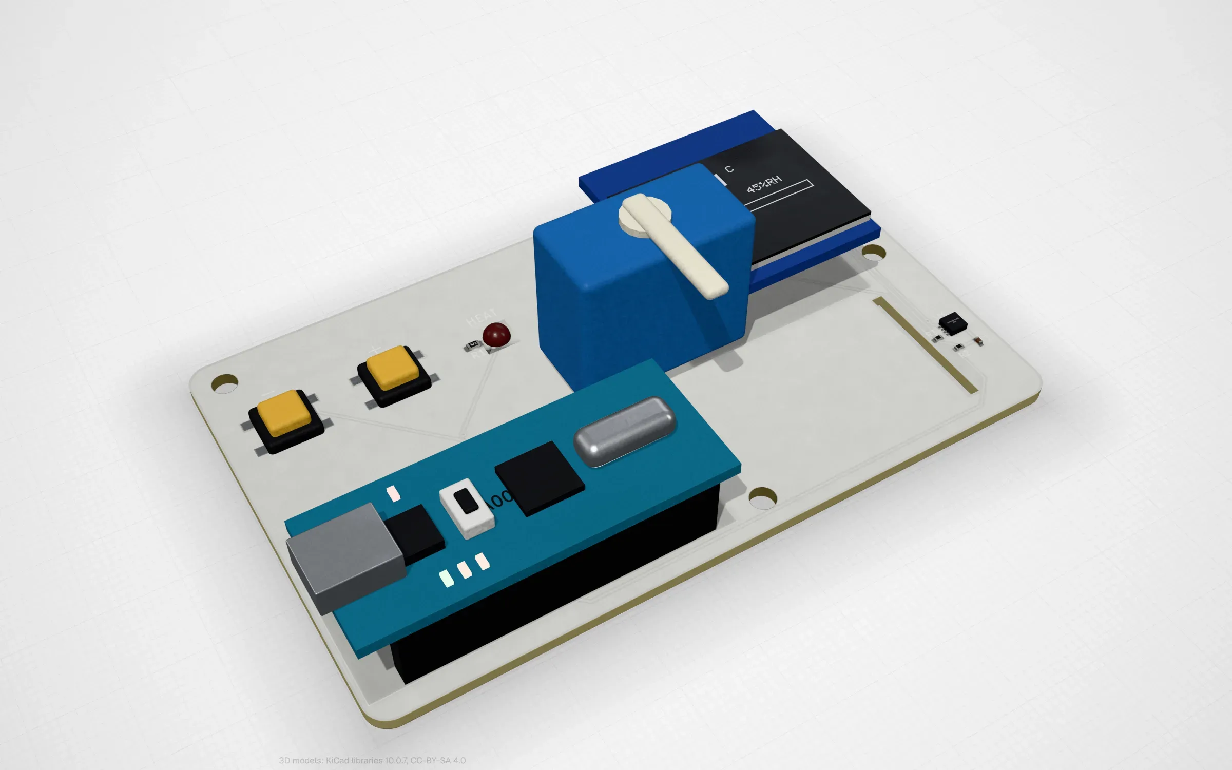
thermostat: Servo on Timer1, an SHT31 on the TWI and the setpoint in the EEPROM.
What is in it
The core. The AVRe+ instruction set, including the ones nobody uses until a library does:
MULSU and the FMUL family, WDR, BREAK, SPM for self-programming and the signature row.
The ports and interrupts. The I/O ports with their pull-ups, INT0 and INT1, the pin change interrupts. On a Nano the pins carry their buses by their functions: A4 and A5 are I²C, D11 and D13 SPI, D0 and D1 the USART, A0 to A5 also the ADC.
The three timers, in every mode. Timer0, Timer1 and Timer2 in every waveform generation mode: normal, CTC, fast PWM, phase correct and, for Timer1, phase and frequency correct, each with its TOP. The compare registers are double buffered as on the chip, the compare outputs toggle, clear and set (PWM inverting and non-inverting) and the flags are raised at MAX, TOP, BOTTOM and each match. Input capture and external clocks are there too. Timers are also where the model saves time: between edges that change something, the counter just runs linearly, so a timer running between events costs little.
The serial buses. USART0 in every asynchronous format and as an SPI master (MSPIM), the SPI in every mode and the TWI as a master, all with their interrupts. A byte arrives when its transfer completes; what’s on the other end of the bus (an OLED, a sensor, a terminal) comes from the board through the lab’s fabric.
The analog side. The ADC with all its channels, its references, the internal temperature sensor and the auto triggers, with conversion timing from the data sheet’s §24.4. The analog comparator. On the magic drawing screen two potentiometers feed the ADC and turning them in the lab is just changing two voltages.
The rest. The EEPROM with its real write time, the watchdog (with reset: the chip restarts and RAM and EEPROM are kept), the clock prescaler, power reduction and every sleep mode. Waking up takes four cycles to the vector, four more from sleep and the oscillator’s start-up time.
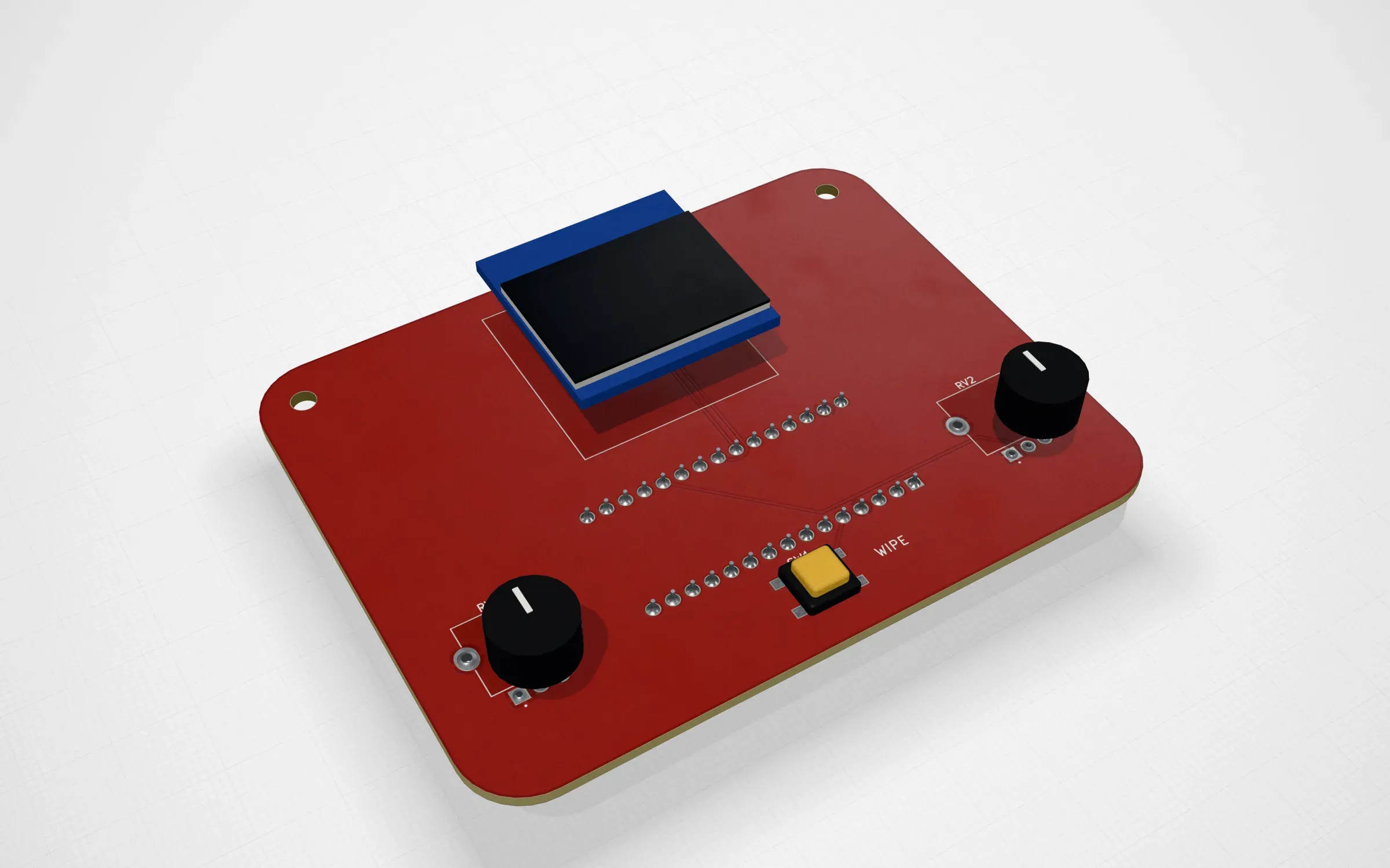
etch-a-sketch: two potentiometers on the ADC, one across and one up and down.
simavr as a reference, not a judge
A model you wrote yourself, checked by programs you wrote yourself, proves very little. So we
compared it with simavr, the AVR simulator a lot of people
use, version 1.8. simavr is GPL, so it is built outside our repository and only its output is
compared. The script (tools/lab/avr-reference) compiles five small sketches with the web app’s
own toolchain, runs each image on simavr and on our model for the same number of cycles and
compares the traces: the USART’s bytes must be equal, each pin’s sequence of levels must agree
and the cycles where the pins change are reported.
The sketches and what came out:
| Sketch | USART | Pins |
|---|---|---|
| serial | 53 bytes equal | |
| interrupts | equal intervals but for 4 cycles per interrupt | |
| pwm | Timer0 periods equal; simavr drives no Timer1 or Timer2 compare output | |
| eeprom | 30 bytes equal | the 16 ms watchdog period equal; our start is 27 ms later |
| servo | 20 ms frames and pulse widths equal; our first frame is 32 ms later |
The bytes are identical everywhere they are compared and the periods agree. Every difference left is a place where simavr departs from the data sheet and in each case we follow the data sheet. I want to be careful here: simavr is a volunteer project that a lot of people rely on and these are small things that most programs never notice. But they are real and each one showed up in a trace:
| simavr 1.8 | Data sheet (DS40002061B) and PCBKit |
|---|---|
| entering an interrupt takes no cycles | four cycles (§6.7) |
| OCnx is set when COMnx is written | at the next BOTTOM in fast PWM (§15.7.3) |
| Timer1’s and Timer2’s compare outputs do not drive their pins | they do |
| writing TCNTn does not block the next compare match | it does (§16.7) |
| an EEPROM write completes at once | 3.4 ms, with EEPE set meanwhile (§8.6.3) |
Together they explain the first table. The interrupt sketch loses four cycles per interrupt on simavr. The eeprom sketch does eight EEPROM writes at 3.4 ms each before it starts its watchdog, so our start is 27 ms later than simavr’s, where the writes are instant. The servo sketch starts 32 ms later on our side because the Servo library writes TCNT1 and on the real chip that write blocks the next compare match, so the first frame comes later. On simavr it doesn’t. After that, the 20 ms frames and the pulse widths are the same on both.
The script stays in the repository and is meant to run whenever someone touches the AVR model, so a change that breaks the agreement shows up as a trace that no longer matches.
What real sketches found in the model
Two of the problems real sketches found were not a simavr question at all, because they were about the world around the chip. A sketch at 115200 baud really runs the USART at 117647 (2.1% fast at 16 MHz) and the lab’s terminal refused it with a ±2% check. A real receiver holds to about ±4% (Table 19-2), so that is the check now. And the weather station crashed after 4 s reading SRAM at 0x4000, far outside the chip’s 2 KB: its 810 bytes of globals plus the SSD1306’s 1 KB buffer left about 200 bytes of stack and it would crash on a real Nano too. In the lab the bad read has an address and a time, which is much easier to find than a real board that just hangs.
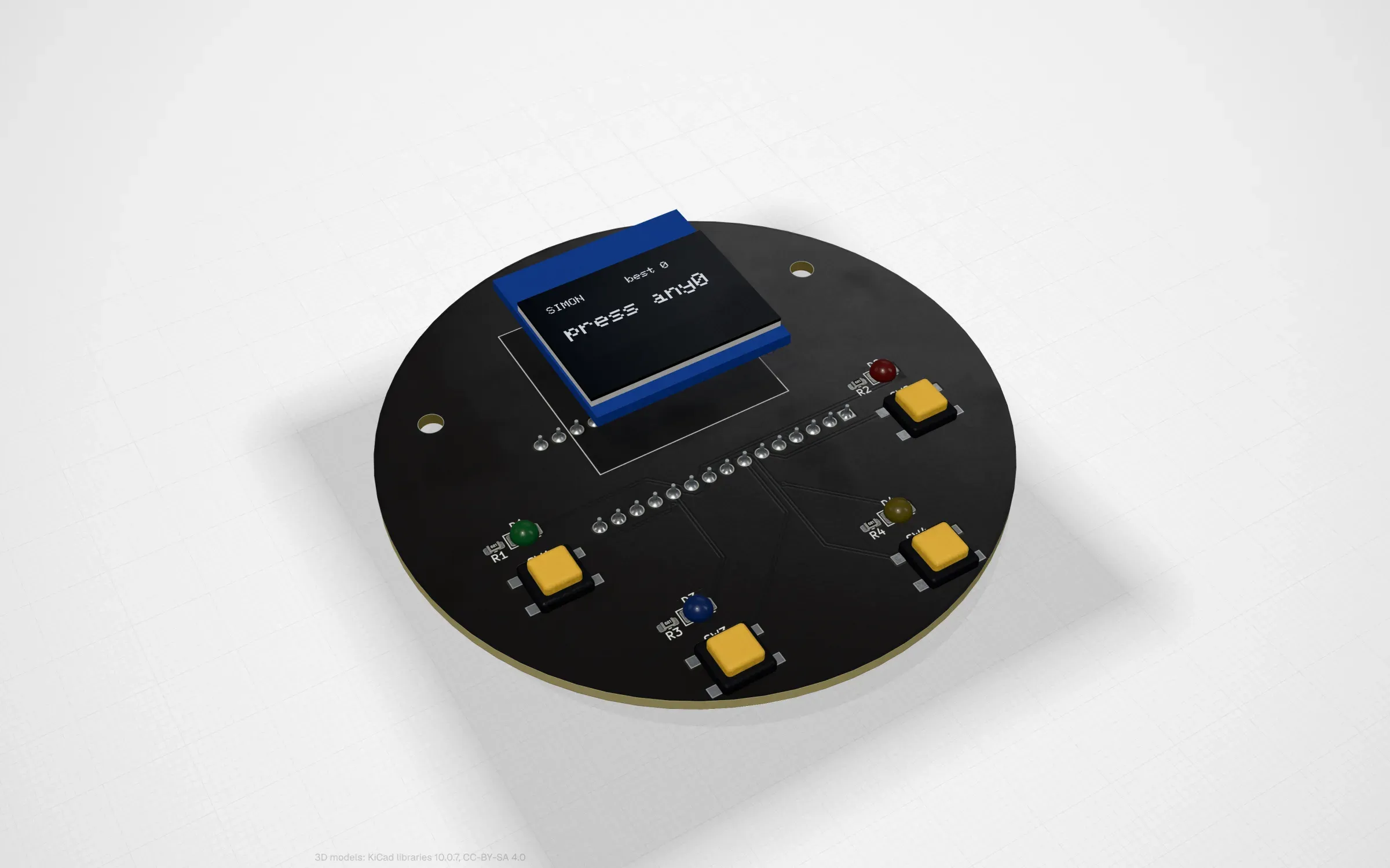
simon: four coloured lights, four buttons and the best round kept in the EEPROM.
What is not done
A few parts of the chip are left out on purpose and each stops the simulation with an error if a program asks for it, rather than doing something quietly wrong:
- Timer2’s asynchronous clock: on a Nano or an Uno the TOSC pins carry the 16 MHz crystal, so there is no watch crystal to run it from.
- The USART’s synchronous mode.
- SPI and TWI as a slave: there is no other controller on the board’s buses.
- debugWIRE.
The power numbers are assumptions, not measurements: 9 mA awake, 1.5 mA in idle sleep and 12 mA peak at 16 MHz, with no measured silicon behind them. And the honest limit of the whole thing: the model is checked against simavr and the data sheet, which covers what we implemented, not complete silicon fidelity. A chip has errata and analog behaviour that no data sheet table describes.
Every one of the twelve Arduino boards runs on this model in the browser and the sketches are in github.com/pcbkit-io/boards. Open the thermostat, cool the room and watch the valve open: that’s Timer1, the TWI and the EEPROM working together on a chip that only exists in your tab.