2 layers99.1 × 45.7 mm

 Zulljon/rover_commander
rover commander pcb project
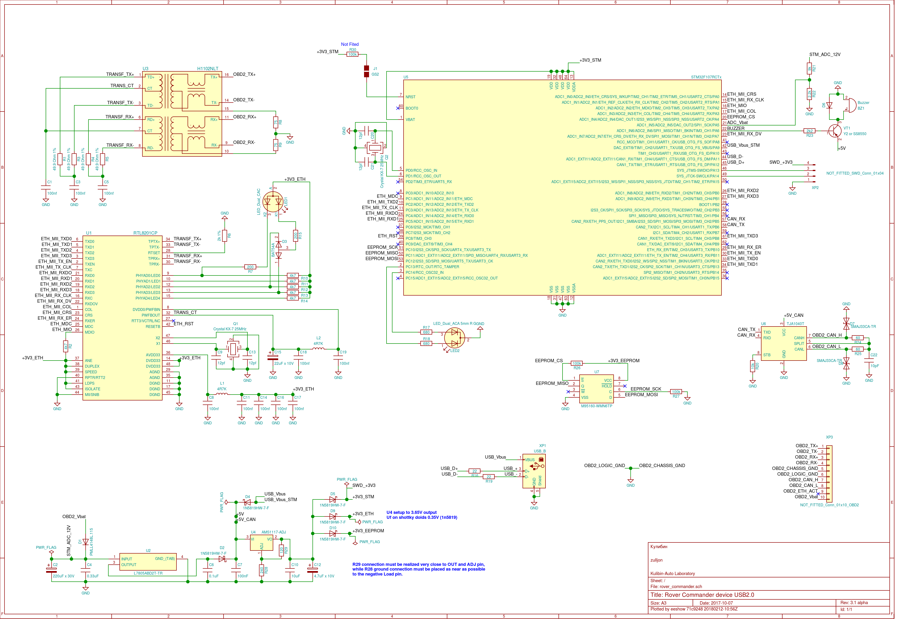
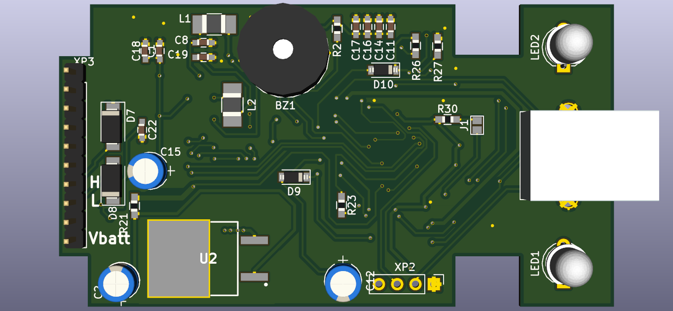
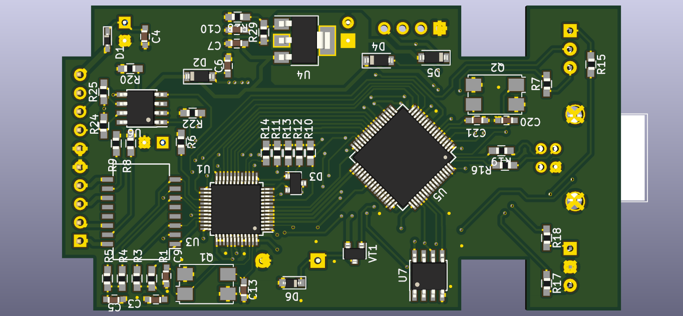
Rover commander is an open-source printed circuit board by Zulljon, from the Zulljon/rover_commander repository on GitHub, published under the LGPL-3.0 licence. It is a 2-layer board of 77 × 42 mm with 83 parts on 85 nets, routed with 1,244 tracks and 105 vias.
It is built around the TJA1040T, AMS1117-ADJ and H1102NLT, with the L7805ABD2T-TR, M95160-WMN6TP and 1N5819HW-7-F-01 among its other parts. Its parts include 31 resistors, 22 capacitors, 13 diodes, 7 ICs and 2 transistors. It belongs with the robots and motor control boards and the STM32 boards of this library.


PCB part of project (source codes unavailable!)
| Qty | Value | Footprint | References |
|---|---|---|---|
| 10 | 100nf | Capacitors_SMD:C_0603_HandSoldering | C1, C3, C5, C8, C11, C14, C16, C17, C18, C19 |
| 6 | 4k7 | Resistors_SMD:R_0603_HandSoldering | R2, R10, R11, R12, R13, R14 |
| 5 | 1N5819HW-7-F | Diodes_SMD:D_SOD-123 | D2, D4, D5, D9, D10 |
| 4 | 12pf | Capacitors_SMD:C_0603_HandSoldering | C9, C13, C20, C21 |
| 4 | 49.9 Ohm 1% | Resistors_SMD:R_0603_HandSoldering | R1, R3, R4, R5 |
| 3 | 100k | Resistors_SMD:R_0603_HandSoldering | R26, R27, R30 |
| 2 | 200 | Resistors_SMD:R_0603_HandSoldering | R7, R15 |
| 2 | 22 | Resistors_SMD:R_0603_HandSoldering | R16, R19 |
| 2 | 2k2 | Resistors_SMD:R_0603_HandSoldering | R22, R23 |
| 2 | 4R7K | Inductors_SMD:L_1210_HandSoldering | L1, L2 |
| 2 | 60 | Resistors_SMD:R_0603_HandSoldering | R24, R25 |
| 2 | 680 | Resistors_SMD:R_0603_HandSoldering | R17, R18 |
| 2 | 75 | Resistors_SMD:R_0603_HandSoldering | R8, R9 |
| 2 | Crystal KX-7 25MHz | Crystals:Crystal_SMD_7050-4pin_7.0x5.0mm | Q1, Q2 |
| 2 | SMAJ33CA-TR | Diodes_SMD:D_SMA | D7, D8 |
| 1 | 0.1uF | Capacitors_SMD:C_0603_HandSoldering | C6 |
| 1 | 0.33uF | Capacitors_SMD:C_0603_HandSoldering | C4 |
| 1 | 100nF | Capacitors_SMD:C_0603_HandSoldering | C7 |
| 1 | 10k | Resistors_SMD:R_0603_HandSoldering | R20 |
| 1 | 10pF | Capacitors_SMD:C_0603_HandSoldering | C22 |
| 1 | 10uF | Capacitors_SMD:C_0603_HandSoldering | C10 |
| 1 | 120 | Resistors_SMD:R_0603_HandSoldering | R29 |
| 1 | 1k | Resistors_SMD:R_0603_HandSoldering | R31 |
| 1 | 220uF x 30V | Capacitors_THT:CP_Radial_D5.0mm_P2.50mm | C2 |
| 1 | 22uF x 10V | Capacitors_THT:CP_Radial_D5.0mm_P2.50mm | C15 |
| 1 | 240 | Resistors_SMD:R_0603_HandSoldering | R28 |
| 1 | 2k 1% | Resistors_SMD:R_0603_HandSoldering | R6 |
| 1 | 4.7uF x 10V | Capacitors_THT:CP_Radial_D5.0mm_P2.50mm | C12 |
| 1 | 9k | Resistors_SMD:R_0603_HandSoldering | R21 |
| 1 | AMS1117-ADJ | TO_SOT_Packages_SMD:SOT-223-3Lead_TabPin2 | U4 |
| 1 | BAT54A | TO_SOT_Packages_SMD:SOT-23 | D3 |
| 1 | Buzzer | Buzzers_Beepers:Buzzer_12x9.5RM7.6 | BZ1 |
| 1 | GS2 | Connectors:GS2 | J1 |
| 1 | H1102NLT | Housings_SOIC:SOIC-16W_7.5x12.8mm_Pitch1.27mm | U3 |
| 1 | L7805ABD2T-TR | zulljon:TO254P1542X460-3N | U2 |
| 1 | LED BLUE | LEDs:LED_0603_HandSoldering | D11 |
| 1 | LED_Dual_ACA 5mm R G | LEDs:LED_D5.0mm-3 | LED2 |
| 1 | LED_Dual_CAC | LEDs:LED_D5.0mm-3 | LED1 |
| 1 | M4 BAV16W or 1N4148WS | Diodes_SMD:D_SOD-323_HandSoldering | D6 |
| 1 | M95160-WMN6TP | Housings_SOIC:SOIC-8_3.9x4.9mm_Pitch1.27mm | U7 |
| 1 | NOT_FITTED_Conn_01x10_OBD2 | Pin_Headers:Pin_Header_Straight_1x10_Pitch2.54mm | XP3 |
| 1 | NOT_FITTED_SWD_Conn_01x04 | Pin_Headers:Pin_Header_Straight_1x04_Pitch2.54mm | XP2 |
| 1 | PMLL4148L.115 | Diodes_SMD:D_SC-80_HandSoldering | D1 |
| 1 | RTL8201CP | Housings_QFP:LQFP-48_7x7mm_Pitch0.5mm | U1 |
| 1 | STM32F107RCTx | zulljon:LQFP-64_10x10mm_Pitch0.5mm_datesheet | U5 |
| 1 | TJA1040T | Housings_SOIC:SOIC-8_3.9x4.9mm_Pitch1.27mm | U6 |
| 1 | USB_B | Connectors:USB_B | XP1 |
| 1 | Y2 or SS8550 | TO_SOT_Packages_SMD:SOT-23 | VT1 |
It measures 77 × 42 mm and has 2 copper layers, 1.6 mm thick.
83 parts, built around the TJA1040T, AMS1117-ADJ, H1102NLT and L7805ABD2T-TR. The full list of its parts is on this page, with links to each part's symbol and footprint where PCBKit's library has them.
From the Zulljon/rover_commander repository on GitHub, at the commit this page was made from: the board is rover_commander.kicad_pcb. PCBKit opens the board in the browser, with nothing to install.
Its repository publishes it under the LGPL-3.0 licence: you may reuse it on that licence's terms (keep the author's notice, and for a copyleft licence share your changes alike).


electrodyssey/lboard2
experimental Spartan-6 sound processing board with XC6SLX9-TQG144 and TLV320AIC3204


twisted-builds-llc/sloppy_holley_flex-over-can
CAN bus input/output module for Holley Terminator X (also HP/Dominator class ECUs).