2 layers98 × 27 mm

 zosko/Grove-KnockKnock
Groove Knock-Knock Sensor for SeeedStudio
Groove knock sensor is an open-source printed circuit board by zosko, from the zosko/Grove-KnockKnock repository on GitHub. It is a 2-layer board of 24 × 20 mm with 5 parts on 3 nets, routed with 8 tracks and 0 vias.
Its parts include 1 resistor, 1 connector and 1 switch. It belongs with the sensors and measurement boards of this library.
A Grove KnockKnock Sensor is a simple device that detects vibrations or shocks from knocking or tapping it. It is basically an electronic switch which normally open. When it detects any shock or vibrations, it closes.
A typical knock sensor consists of the main sensing element, which is a conductive vibrating spring, a Resistor and three Pins. The three pins of the Knock Sensor Module are GND, +5V and Sig. The following image shows the components of a Knock Sensor Module as well as the pins on it.
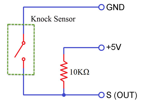
If you take a look at the schematic of the knock sensor, it basically consists of a switch and a resistor. The Vibrating Spring is represented as a switch here. The output pins of the sensor is pulled HIGH with the help of a 10KΩ Pull-up resistor. Under normal condition i.e. when there is no shock or vibrations, the output of the Knock Sensor is HIGH. When the sensor detects any vibrations or shocks, the vibrating spring i.e. switch closes and hence the output of the sensor (at the output pin) will become LOW.
Now that we have seen the components of a knock sensor and how a typical knock sensor works, let us proceed with interfacing. I have designed a simple circuit using Arduino, Knock Sensor and an LED where the LED is turned on by Arduino when the knock sensor detects any vibrations.
Also the information of the knock sensor (knock or no knock) is displayed on the Arduino IDE’s serial monitor.
const int knockPin = 8;

int knockVal = HIGH;
boolean knockAlarm = false;
unsigned long prevKnockTime;
int knockAlarmTime = 100;

void setup () {
  Serial.begin(9600);
  pinMode(knockPin, INPUT) ;
}
void loop () {
  knockVal = digitalRead(knockPin);

  if (knockVal == LOW) {
    prevKnockTime = millis();
    if (!knockAlarm) {
      Serial.println("KNOCK, KNOCK");
      knockAlarm = true;
      delay(1000);
    }
  } else {
    if( (millis() - prevKnockTime) > knockAlarmTime && knockAlarm) {
Serial.println("No Knocks");The main purpose of the Knock Sensor is to detect vibrations or shocks. Hence, the main application of such sensor can be in Door Knock System, where when a door is knocked, a notifications (like a light or a buzzer) can be activated.
| KiCad View | Seeed PCB |
|---|---|
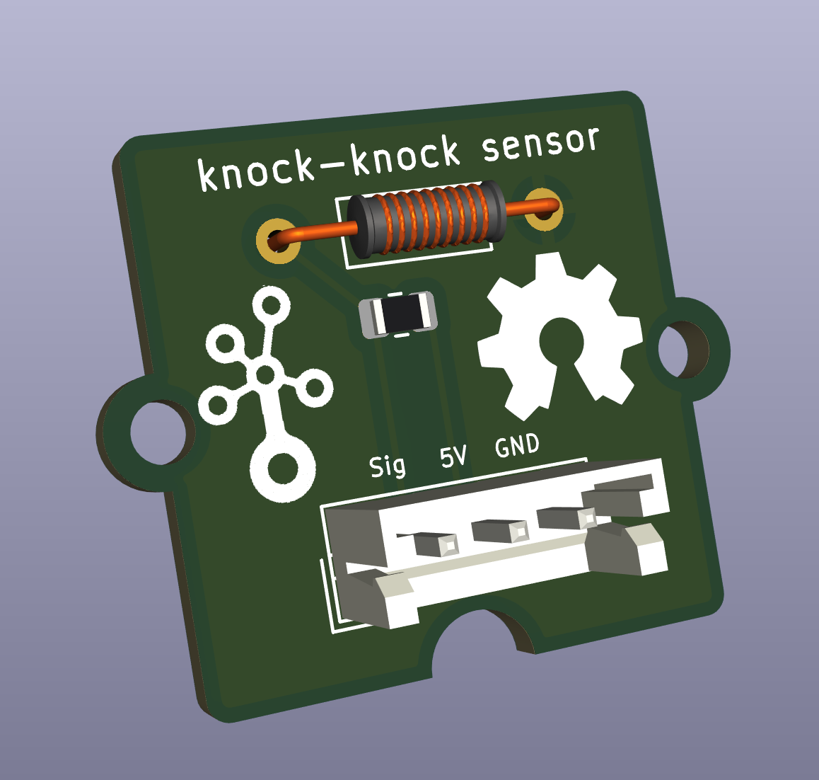 | 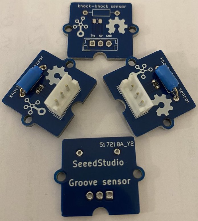 |
For PCB design i will use services from SeeedFusion.
Seeed Fusion PCB Assembly Service offers one-stop prototyping for PCB manufacture, PCB assembly and as a result they produce superior quality PCBs and Fast Turnkey PCBA from 7 working days. When you prototype with Seeed Fusion, they can definitely provide Free DFA and Free functional tests for you!
Check out their website to know about their manufacturing capabilities and service. https://www.seeedstudio.com/pcb-assembly.html
| Qty | Value | Footprint | References |
|---|---|---|---|
| 1 | GROVE-SILK-BIG | U$3 | |
| 1 | 10K | Resistor_SMD:R_0805_2012Metric | R1 |
| 1 | Connector | Connector_JST:JST_EH_B3B-EH-A_1x03_P2.50mm_Vertical | J1 |
| 1 | Vibration Switch | Inductor_THT:L_Axial_L5.3mm_D2.2mm_P10.16mm_Horizontal_Vishay_IM-1 | SW1 |
The 4 most common of 5 parts.

joypad-ai/joypad-os
Universal controller firmware for building adapters, dongles, and custom controllers.

OLIMEX/OLINUXINO
OLINUXINO is Open Source / Open Hardware, low cost from EUR 24 Linux Industrial grade Single Board Computer capable to operate -25+85C

jamro/tiny-engineer
A small desktop robot that brings an AI coding assistant to life, physically acting out when it reads files, thinks, writes code, and finishes work.

hackclub/OnBoard
💡 Join 1,000 teenagers and make your first PCB with a $100 grant!


Luos-io/luos_engine
Open-source and real-time orchestrator for cyber-physical-systems, to easily design, test and deploy embedded applications and digital twins.
It measures 24 × 20 mm and has 2 copper layers, 1.6 mm thick.
5 parts. The full list of its parts is on this page, with links to each part's symbol and footprint where PCBKit's library has them.
From the zosko/Grove-KnockKnock repository on GitHub, at the commit this page was made from: the board is KiCad/groove-knock-sensor.kicad_pcb and its schematic KiCad/groove-knock-sensor.kicad_sch. PCBKit opens the board in the browser, with nothing to install.
Its repository states no licence, so its author keeps all rights: ask zosko before reusing the design.