
2 layers65 × 56 mm

 zeldin/CartridgeBreakout4
Breakout PCB for C64 cartridges
CartridgeBreakout is an open-source printed circuit board by zeldin, from the zeldin/CartridgeBreakout repository on GitHub. It is a 2-layer board of 99 × 75 mm with 23 parts on 73 nets, routed with 443 tracks and 0 vias.
It is built around the LTL-4222 and LTL-4232. Its parts include 10 connectors, 2 resistors and 2 diodes. It belongs with the retro computing and games boards of this library.
This is a PCB to break out the signals of a 44-contact 2.54 mm card edge connector, as used in cartridges for the C64, to pin headers. It was designed for use with the Orange Cartridge, but can be used with any C64 cartridge, or even other compatible card edge devices.
The board can be used for testing, debugging and prototyping cartridges and FPGA cartridge gateware and software.
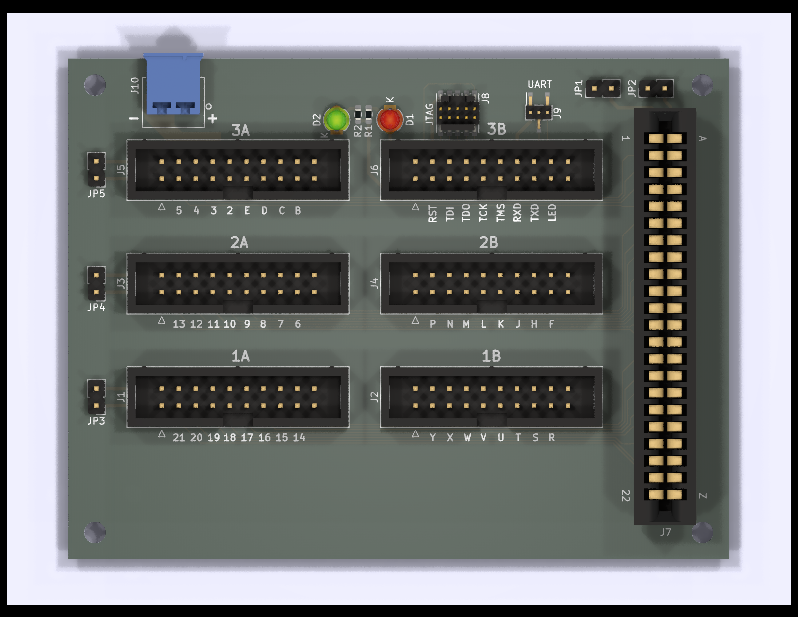
40 of the 44 contacts are routed to individual pins compatible with IDC or Dupont wiring.
The 4 corner contacts are instead connected to a ground plane which is available on 40 pins, one for each signal pin.
There is a 5V power plane which can be used to inject power into contacts 2 and 3, or just one of them if so desired.
There is a 5-signal JTAG/SWD breakout from a 2x5 1.27 mm pin header, as a wired side channel to the cartridge.
There is also a 2-signal UART breakout from a 1x3 1.27 mm pin header, likewise a wired side channel.
There are two LEDs which can be controlled with a single pin, to support semi-automated testing setups.
| Qty | Value | Footprint | References |
|---|---|---|---|
| 6 | Conn_02x10_Odd_Even | Connector_IDC:IDC-Header_2x10_P2.54mm_Vertical | J1, J2, J3, J4, J5, J6 |
| 5 | Jumper | Connector_PinHeader_2.54mm:PinHeader_1x02_P2.54mm_Vertical | JP1, JP2, JP3, JP4, JP5 |
| 4 | MountingHole | MountingHole:MountingHole_3.2mm_M3 | H1, H2, H3, H4 |
| 2 | 130 | Resistor_SMD:R_0603_1608Metric_Pad0.98x0.95mm_HandSolder | R1, R2 |
| 1 | Conn_01x02 | TE:284512-2 | J10 |
| 1 | Conn_01x03 | Connector_PinHeader_1.27mm:PinHeader_1x03_P1.27mm_Vertical_SMD_Pin1Right | J9 |
| 1 | Conn_02x05_Odd_Even | samtec:FTSH-105-XX-X-DV | J8 |
| 1 | EXPANSION_PORT_C64_EDGE | TE:TE_5530843-4 | J7 |
| 1 | LTL-4222 | LED_THT:LED_D3.0mm | D1 |
| 1 | LTL-4232 | LED_THT:LED_D3.0mm | D2 |

google/mozc-devices
Circuit diagrams and firmware source code for Gboard DIY keyboards


Duet3D/Duet-2-Hardware
The KiCAD source for the Duet 3d printer controller see www.duet3d.com
It measures 99 × 75 mm and has 2 copper layers, 1.6 mm thick.
23 parts, built around the LTL-4222 and LTL-4232. The full list of its parts is on this page, with links to each part's symbol and footprint where PCBKit's library has them.
From the zeldin/CartridgeBreakout repository on GitHub, at the commit this page was made from: the board is CartridgeBreakout.kicad_pcb. PCBKit opens the board in the browser, with nothing to install.
Its repository states no licence, so its author keeps all rights: ask zeldin before reusing the design.