2 layers19 × 76 mm
Sub
google/mozc-devices
Circuit diagrams and firmware source code for Gboard DIY keyboards
15 parts3kApache-2.0

 zaxour/9Pin_BreakoutEx4
Breakout board for 9 pin mini DIN connectors with additional features for audio and sync.
MiniDIN9 Breakout is an open-source printed circuit board by zaxour, from the zaxour/9Pin_BreakoutEx repository on GitHub. It is a 2-layer board of 21.6 × 22.2 mm with 15 parts on 11 nets, routed with 72 tracks and 9 vias.
Its parts include 11 connectors, 2 resistors and 1 capacitor. It belongs with the interfaces and adapters boards of this library.
Breakout board for 9 pin mini DIN connectors with additional features for audio and sync.
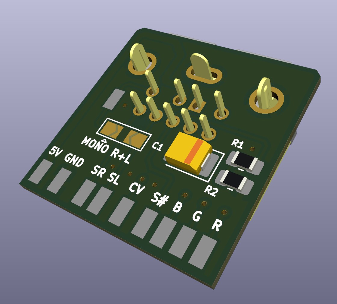
Leaving the jumpers un-bridged and components empty means the board will act like a standard 9 pin breakout DIN.
If attaching to a system that doesn't have composite and only has a 5V TTL level sync, use the following BOM:
C1: 220uF 6.3V Tantalum 3528 size capacitor R1: 620 Ohm 1/8W 0603 size Resistor R2: 86.6 Ohm 1/8 0603 size Resistor
RGB mods for older consoles tend to make the user decide between Composite Video level sync or TTL sync. With this breakout, simply install the resistors and capacitor (value indicated on bottom silkscreen) and use the TTL sync from the RGB modification. This will simultaneously deliver a proper sync voltage to the Composite Video pin on the DIN for using HD Retrovision cables. ***ENSURE THE RGB MOD CAN DRIVE TWO 75 OHM LOADS (Such as THS7374, THS7314 or similar) ***
The solder jumper for audio can be used as follows: -Right: Connects Right and Left audio nodes, passes to both pins. -Left: Connects Right audio to the Mono pin
Both jumpers can be soldered to make sure a mono audio signal goes to all of the audio pins.
| Qty | Value | Footprint | References |
|---|---|---|---|
| 10 | SMD_Conn_01x01 | MyLibrary:SolderWirePad_1x01_SMD_1x2mm | J1, J2, J3, J4, J5, J6, J7, J8, J9, J10 |
| 2 | R_US | Resistor_SMD:R_0805_2012Metric_Pad1.20x1.40mm_HandSolder | R1, R2 |
| 1 | C_Polarized_US | Capacitor_Tantalum_SMD:CP_EIA-3528-15_AVX-H_Pad1.50x2.35mm_HandSolder | C1 |
| 1 | MD-90SM_MD2 | SnapEDA:CUI_MD-90SM | J11 |
| 1 | SolderJumper_3_Open | Jumper:SolderJumper-3_P2.0mm_Open_TrianglePad1.0x1.5mm | JP1 |
google/mozc-devices
Circuit diagrams and firmware source code for Gboard DIY keyboards

hoglet67/RGBtoHDMI
Bare-metal Raspberry Pi project that provides pixel-perfect sampling of Retro Computer RGB/YUV video and conversion to HDMI

mntmn/amiga2000-gfxcard
MNT VA2000, an Open Source Amiga 2/3/4000 Graphics Card (Zorro II/III), written in Verilog

hackclub/OnBoard
💡 Join 1,000 teenagers and make your first PCB with a $100 grant!

kenp-io/not-for-airpods-repairs
The content of this repository is licensed under the WTFPL License. Please have a close look at the terms before using this material.

Luos-io/luos_engine
Open-source and real-time orchestrator for cyber-physical-systems, to easily design, test and deploy embedded applications and digital twins.

Chrismettal/EleLab_v2
Cheap DIY lab system for hobbyists and the tinkering folk

It measures 21.6 × 22.2 mm and has 2 copper layers, 0.81 mm thick.
15 parts. The full list of its parts is on this page, with links to each part's symbol and footprint where PCBKit's library has them.
From the zaxour/9Pin_BreakoutEx repository on GitHub, at the commit this page was made from: the board is MiniDIN9 Breakout.kicad_pcb and its schematic MiniDIN9 Breakout.kicad_sch. PCBKit opens the board in the browser, with nothing to install.
Its repository states no licence, so its author keeps all rights: ask zaxour before reusing the design.