2 layers19 × 76 mm
Sub
google/mozc-devices
Circuit diagrams and firmware source code for Gboard DIY keyboards
15 parts3kApache-2.0

 zacianculovici/hackaclock
My Stardance BLARE alarm clock!!!
Hackaclock is an open-source printed circuit board by zacianculovici, from the zacianculovici/hackaclock repository on GitHub, published under the MIT licence. It is a 2-layer board of 95 × 65 mm with 15 parts on 15 nets, routed with 60 tracks and 3 vias.
Its parts include 6 switches, 1 IC and 1 connector. It belongs with the ESP32 and RISC-V boards of this library.
My Stardance BLARE alarm clock!!!
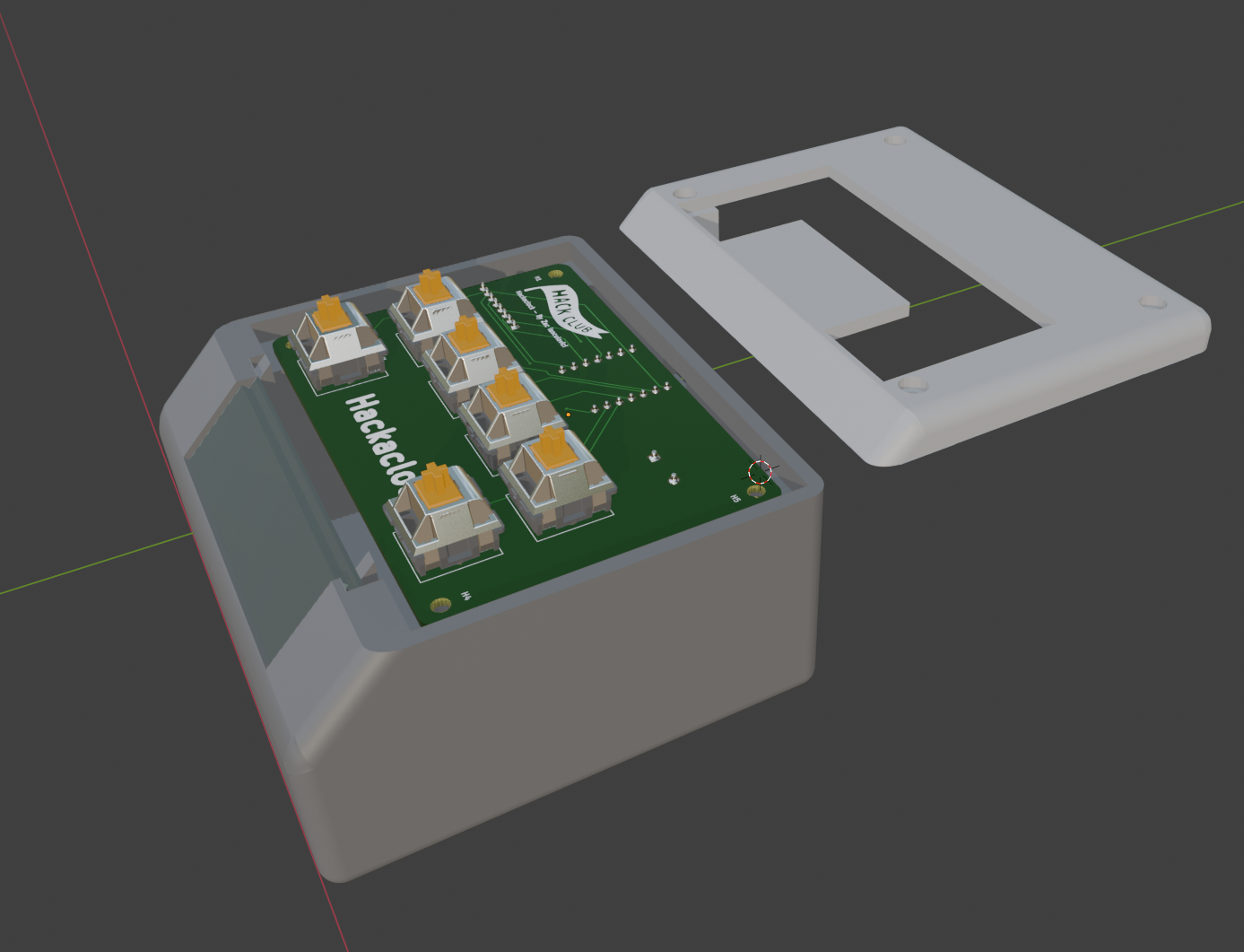
Really, I just saw the BLARE mission and thought it was really cool, but I made the case inspired by one of those old alarm clocks with the angled screens. I also added a cool cutout and some bevelling to make it look nice.
I ran into some pretty tough issues while doing CAD. I made a dumb decision at the start to use blender for my CAD even though it's not exactly a CAD program. Loads of non-manifold errors and geometry issues (that might just be why my commit history looks terrible). I spent over 13 hours just getting the CAD done! Despite these problems, I am still very happy with the result and the CAD (in my humble opinion) looks great.
I am using the most barebones firmware to begin, but I will make it super cool after I build. Currently it only gets the local time via WiFi with no fallback, but I will eventually add:
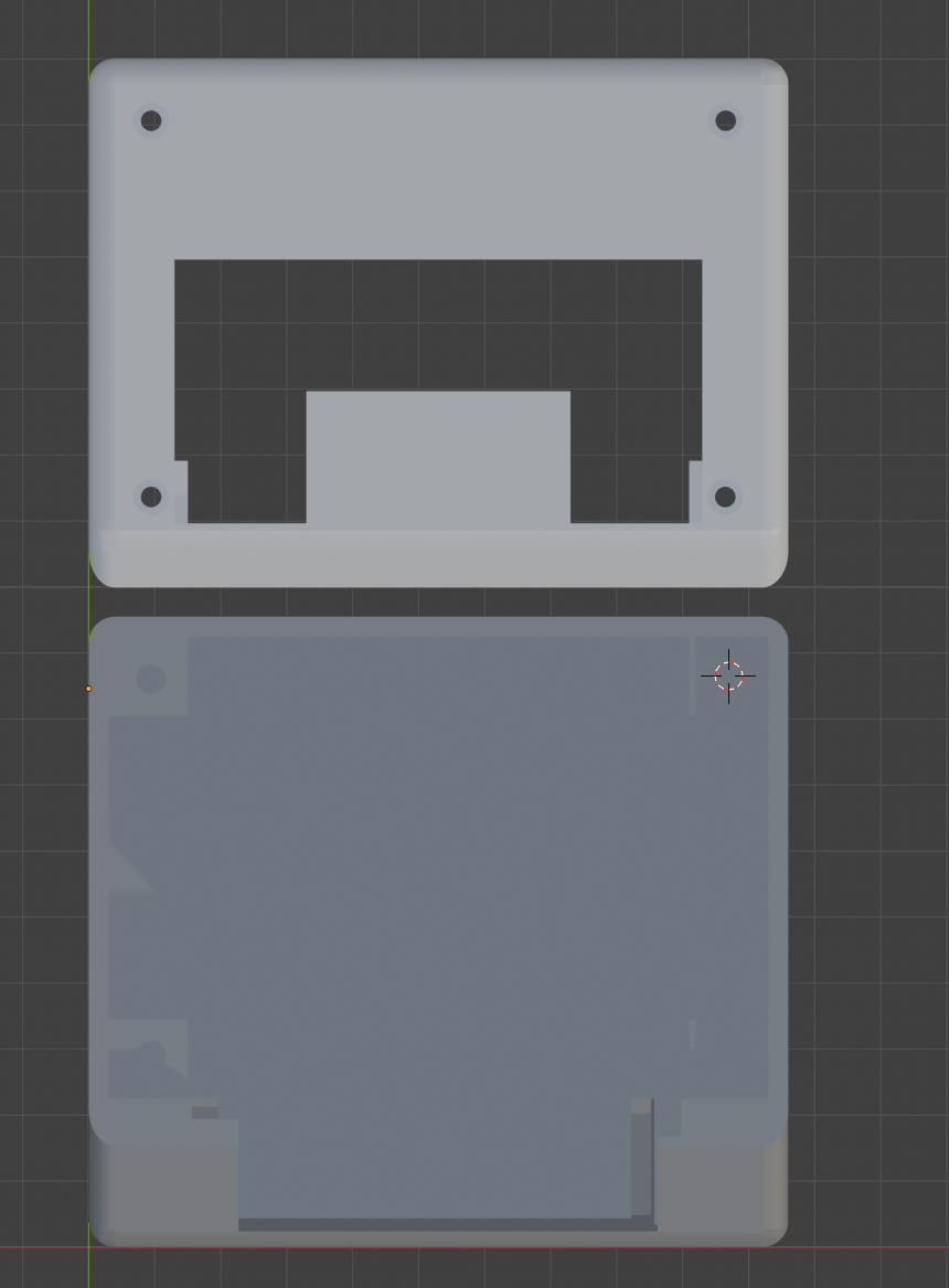
The CAD is a very simple (13h worth of simple) box and lid with a slot for the display and supports for the PCB.
Here is the Schematic and PCB layout for hackaclock.
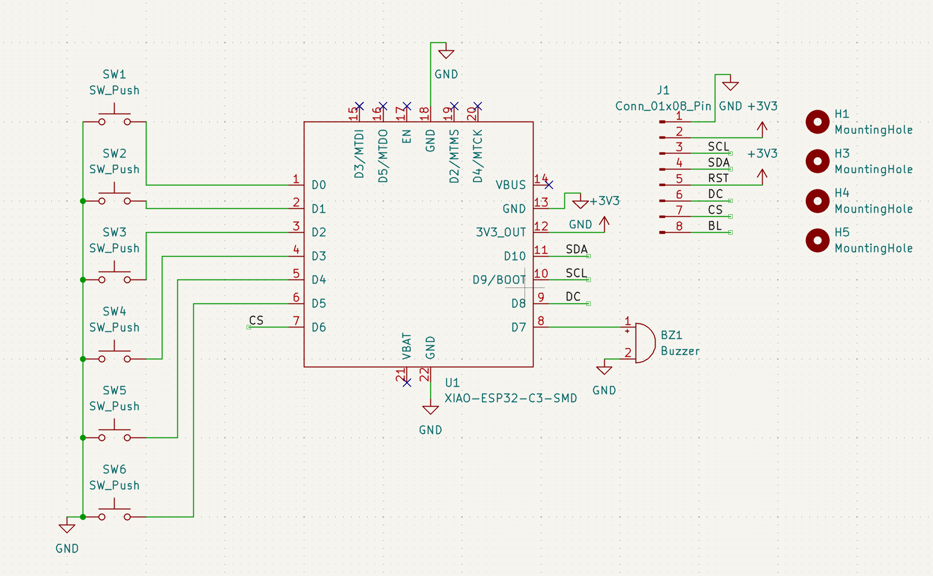
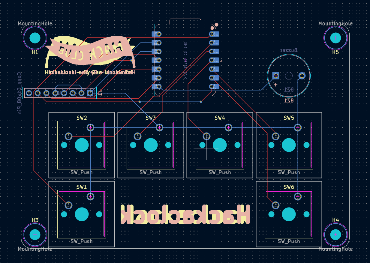
| Qty | Value | Footprint | References |
|---|---|---|---|
| 6 | SW_Push | Library:SW_Cherry_MX_1.00u_PCB | SW1, SW2, SW3, SW4, SW5, SW6 |
| 4 | MountingHole | MountingHole:MountingHole_3.2mm_M3 | H1, H3, H4, H5 |
| 2 | LOGO | LOGO | Hackaclock - By Zac Ianculovici, Hackaclock - By Zac Ianculovici |
| 1 | Buzzer | Buzzer_Beeper:Buzzer_12x9.5RM7.6 | BZ1 |
| 1 | Conn_01x08_Pin | Connector_PinSocket_2.54mm:PinSocket_1x08_P2.54mm_Vertical | J1 |
| 1 | XIAO-ESP32-C3-SMD | Seeed_Studio_XIAO_Series:XIAO-ESP32-C3-DIP | U1 |
It measures 95 × 65 mm and has 2 copper layers, 1.6 mm thick.
15 parts. The full list of its parts is on this page, with links to each part's symbol and footprint where PCBKit's library has them.
From the zacianculovici/hackaclock repository on GitHub, at the commit this page was made from: the board is PCB/hackaclock/hackaclock.kicad_pcb and its schematic PCB/hackaclock/hackaclock.kicad_sch. PCBKit opens the board in the browser, with nothing to install.
Its repository publishes it under the MIT licence: you may reuse it on that licence's terms (keep the author's notice, and for a copyleft licence share your changes alike).
google/mozc-devices
Circuit diagrams and firmware source code for Gboard DIY keyboards

hoglet67/RGBtoHDMI
Bare-metal Raspberry Pi project that provides pixel-perfect sampling of Retro Computer RGB/YUV video and conversion to HDMI

mntmn/amiga2000-gfxcard
MNT VA2000, an Open Source Amiga 2/3/4000 Graphics Card (Zorro II/III), written in Verilog

hackclub/OnBoard
💡 Join 1,000 teenagers and make your first PCB with a $100 grant!

kenp-io/not-for-airpods-repairs
The content of this repository is licensed under the WTFPL License. Please have a close look at the terms before using this material.

Luos-io/luos_engine
Open-source and real-time orchestrator for cyber-physical-systems, to easily design, test and deploy embedded applications and digital twins.

Chrismettal/EleLab_v2
Cheap DIY lab system for hobbyists and the tinkering folk
