Skip to the content
2 layers70 × 85 mmXkong13 battlebot, the printed circuit board in 3D

ESP32-based Wi-Fi-controlled antweight combat robot featuring two-motor differential drive, custom PCB design, a servo-actuated weapon, and integrated safety mechanisms.

Size
70 × 85 mm
Copper layers
2
Thickness
1.6 mm
Parts
30
Nets
58
Pads
184
Tracks, vias
245, 62
Pours
2
Routed
Yes
KiCad
KiCad 10.0 (file 20260206)
Created
21 Sep 2026
Updated
21 Sep 2026

Overview

Xkong13 battlebot is an open-source printed circuit board by yuxinz310, from the yuxinz310/antweight-battlebot repository on GitHub. It is a 2-layer board of 70 × 85 mm with 30 parts on 58 nets, routed with 245 tracks and 62 vias.

It is built around the ESP32-S2-WROVER-I(4M), L298N and AMS1117-3.3, with the AMS1117-5.0 among its other parts. Its parts include 8 capacitors, 5 resistors, 5 ICs and 4 connectors. It belongs with the robots and motor control boards and the ESP32 boards of this library.

Main components

4

README

README.md

Antweight Battlebot

An ESP32-S3 robot with browser-based wireless control, differential drive, and a servo-actuated front lifter. Built for UIUC ECE 445, Spring 2026.
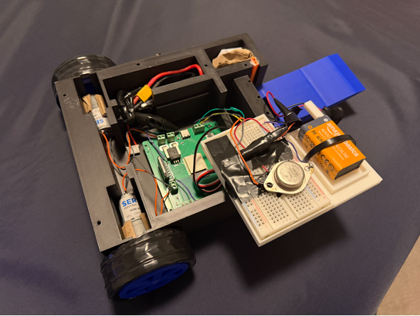
Assembled robot

Project overview

The controller hosts a Wi-Fi access point and serves its own control page. Operators can drive with keyboard commands, select three speed levels, adjust motor trim without reflashing, and command synchronized servo presets. A custom KiCad board integrates the control and electrical interfaces.

The main integration challenge was servo-induced power droop: the final report describes an approximately 1.44 V drop on the controller rail that reset the ESP32. Separating the servo supply from the logic supply resolved the reported instability.

Explore the project

AreaContents
FirmwareArduino sketch, setup, GPIO mapping, HTTP commands, and implementation limitations
HardwareKiCad project, schematic, PCB, component library, and manufacturing exports
Final reportArchitecture, power redesign, verification, and costs
Design documentEarlier design and requirements
PresentationProject presentation material
Engineering notebookTwelve weekly entries and supporting figures
ArchiveHistorical backups and alternate exports, retained for traceability

Reported prototype results

These are historical results from the final report, not measurements reproduced from this checkout.

MeasurementReported result
Average command response78 ms
Straight-line drive1 m in 2.34 s (about 0.43 m/s average)
Lifter extension0.31 s
Lifted loadApproximately 2 lb, above 10 mm
Endurance8.6 minutes with 26 actuations
Controller rail3.315 V idle; 3.310 V during motion

Implementation status

The committed firmware implements drive control, servo presets, live trim, and a JSON status endpoint. Its current display is a software estimate based on commanded motor state, not a sensor reading.

The report describes a communication-loss stop within 250 ms. The committed sketch has browser-side stop requests on key release/focus loss, but no firmware command-timeout watchdog: its loop only services HTTP requests. A lost connection can therefore leave the last motor command active. The report's failsafe result should not be treated as a verified feature of this source revision. See firmware notes before operating hardware.

Credits

Yuxin Zhang, Wenhao Zhang, and Xiangyi Kong — ECE 445 Team 5. Original reports and notebook entries are preserved. Third-party component-library terms remain with the hardware files.

Parts

30
QtyValueFootprintReferences
522 uFCapacitor_SMD:C_0805_2012Metric_Pad1.18x1.45mm_HandSolderC1, C5, C7, C8, C13
4MountingHoleMountingHole:MountingHole_3.2mm_M3H1, H2, H3, H4
310kResistor_SMD:R_0805_2012MetricR1, R2, R5
21 uFCapacitor_SMD:C_0805_2012Metric_Pad1.18x1.45mm_HandSolderC3, C6
25.1kResistor_SMD:R_0805_2012MetricR6, R7
2SW_PushButton_Switch_THT:SW_TH_Tactile_Omron_B3F-100xBTMDE1, RST1
2Screw_Terminal_01x03TerminalBlock_4Ucon:TerminalBlock_4Ucon_1x03_P3.50mm_HorizontalSERVO_MOTOR1, SERVO_MOTOR2
10.1uFCapacitor_SMD:C_0805_2012Metric_Pad1.18x1.45mm_HandSolderC12
1ACS756xCB-050B-PFFSensor_Current:Allegro_CB_PFFU2
1AMS1117-3.3Package_TO_SOT_SMD:SOT-223-3_TabPin2U3
1AMS1117-5.0Package_TO_SOT_SMD:SOT-223-3_TabPin2U4
1ESP32-S2-WROVERRF_Module:ESP32-S2-WROVERU5
1L298NPackage_TO_SOT_THT:TO-220-15_P2.54x5.08mm_StaggerOdd_Lead4.58mm_VerticalU1
1Motor1_Terminal_01x02TerminalBlock_4Ucon:TerminalBlock_4Ucon_1x02_P3.50mm_HorizontalJ1
1Motor2_Terminal_01x02TerminalBlock_4Ucon:TerminalBlock_4Ucon_1x02_P3.50mm_HorizontalJ3
1Screw_Terminal_01x02TerminalBlock_4Ucon:TerminalBlock_4Ucon_1x02_P3.50mm_HorizontalJ2
1USB_C_Receptacle_USB2.0_16PConnector_USB:USB_C_Receptacle_G-Switch_GT-USB-7010ASVJ4

Similar boards

  • 2 layers99.9 × 99.9 mmMaquina compostaje, the printed circuit board in 3D

    Maquina compostaje

    dani0421/Compostaje

    El SDA se conecta al pin 33 del ESP32 y el SCL al pin 36 de ESP32, cabe resaltar que en la placa no quedaran orificios para la pantalla, unicamente los pines para hacer la conexión.

    103 parts
  • 4 layers142.3 × 80.5 mmFinal Version, the printed circuit board in 3D

    Final Version

    elshazlio/ecng4504-maze-solver_team_5

    ECNG 4504 (AUC, Spring 2026): autonomous maze-learning & solving robot — MCU (Arduino), Python BLE host app, KiCAD/docs, team deliverables. Single monorepo per course charter.

    99 partsMIT
  • 2 layersEsp, the printed circuit board in 3D

    Esp

    DaLumberjack/Communifarm-PCB

    homeassistant-pcb

    95 parts
  • 2 layers58.4 × 109.9 mmEsp.seq, the printed circuit board in 3D

    Esp.seq

    amonbenson/esp.seq

    Modular MIDI to CV Converter using the ESP32-S2

    193 parts
  • 2 layers101.9 × 57.4 mmEsp gateway, the printed circuit board in 3D

    Esp gateway

    Strat00s/esp-gateway

    All-in-One ESP32 gateway.

    45 partsGPL-3.0
  • 2 layers49.5 × 86 mmWirelessMD, the printed circuit board in 3D

    WirelessMD

    saiaravind19/Wireless_Motor_Driver

    Wireless motor driver

    30 parts1
  • 2 layers131.5 × 133.3 mmIR array sensor, the printed circuit board in 3D

    IR array sensor

    Vulcan758/My-PCB-Designs-

    all the designs I have so far

    65 parts

Questions

How big is the Xkong13 battlebot PCB?

It measures 70 × 85 mm and has 2 copper layers, 1.6 mm thick.

What parts does the Xkong13 battlebot use?

30 parts, built around the ESP32-S2-WROVER-I(4M), L298N, AMS1117-3.3 and AMS1117-5.0. The full list of its parts is on this page, with links to each part's symbol and footprint where PCBKit's library has them.

Where can I download the Xkong13 battlebot KiCad files?

From the yuxinz310/antweight-battlebot repository on GitHub, at the commit this page was made from: the board is hardware/xkong13_battlebot/xkong13_battlebot.kicad_pcb and its schematic hardware/xkong13_battlebot/xkong13_battlebot.kicad_sch. PCBKit opens the board in the browser, with nothing to install.

Can I use the Xkong13 battlebot design in my own project?

Its repository states no licence, so its author keeps all rights: ask yuxinz310 before reusing the design.