2 layers15.5 × 8 mm
 ytsurui/SwitchDecoder31
NMRA DCC Compatible Accessory Decoder
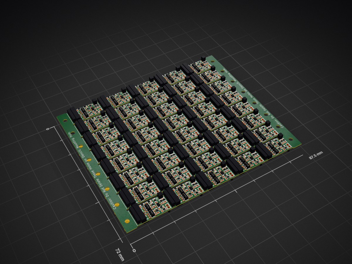
Switchdecoder3 is an open-source printed circuit board by ytsurui, from the ytsurui/SwitchDecoder3 repository on GitHub, published under the MIT licence. It is a 2-layer board of 87.5 × 72 mm with 1,296 parts on 32 nets, routed with 8,840 tracks and 520 vias.
It is built around the ATTINY406-MN, SS2040FL and DMG6601LVT, with the 2SC4116 and PMBT3904VS among its other parts. Its parts include 440 resistors, 280 connectors, 200 diodes, 160 capacitors and 160 transistors. It belongs with the AVR (ATmega, ATtiny) boards of this library.


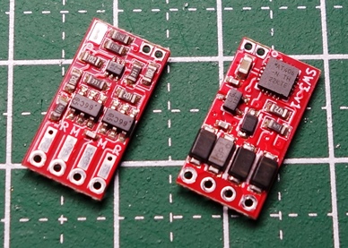
NMRA DCC規格のアクセサリパケットを受信して、直流二線式のポイント線路を動作させることができるアクセサリデコーダです。
本リポジトリには、基板設計データとファームウェア、動作確認用ファームウェアが含まれています。
設定したアクセサリアドレスに応じたDCCパケットを受信すると、ポイント線路を動作させます。
通電開始時にPROG端子に取り付けた配線をどちらかの線路に接触させることで、プログラムモードで起動します。
プログラムモードで起動している間に、同一のアクセサリアドレスに対する操作を連続して3回以上送信することで、設定されているアクセサリアドレスを送信したものに変更することができます。
また、CV値の書き込みにより、通電時間や通電開始までの遅延時間など、細かい動作の調整や、設定のリセットも可能です。
アクセサリアドレス「1」固定でDCCパケットを受信して動作できる機能と、PROG端子を線路に接触させると約1秒おきにポイント線路の転換動作を行うようにプログラムを作成してあります。
このファームウェアを書き込むことで、SwitchDecoder3基板のDCC入力、PROG端子、モータードライバ回路のすべてをテストすることができます。
| Qty | Value | Footprint | References |
|---|---|---|---|
| 160 | 102 | footprint:R_1608 | R11, R13, R102, R103, R106, R107, R113, R114, R117, R118, R121, R123, R126, R129, R135, R136 +144 |
| 160 | 104 | footprint:R_1608 | R1, R10, R100, R101, R109, R110, R111, R112, R119, R120, R127, R128, R131, R132, R133, R134 +144 |
| 160 | PAD | footprint:PAD_2.2x0.8_SMD | P1, P100, P101, P102, P106, P107, P108, P109, P110, P111, P113, P114, P120, P121, P122, P123 +144 |
| 160 | SS2040FL | footprint:PMDU | D1, D11, D101, D102, D103, D104, D106, D107, D108, D109, D111, D112, D113, D114, D116, D117 +144 |
| 80 | 104 | footprint:C_1005 | C1, C11, C101, C102, C105, C106, C109, C111, C113, C115, C117, C119, C121, C122, C125, C126 +64 |
| 80 | 331 | footprint:R_1608 | R14, R15, R104, R105, R115, R116, R124, R125, R137, R138, R148, R149, R159, R160, R170, R171 +64 |
| 80 | DMG6601LVT | footprint:SOT-23-6 | Q1, Q10, Q101, Q102, Q104, Q106, Q109, Q110, Q113, Q114, Q117, Q118, Q121, Q122, Q124, Q126 +64 |
| 40 | 182 | footprint:C_1005 | C12, C100, C107, C108, C112, C116, C120, C127, C128, C132, C136, C140, C147, C148, C152, C156 +24 |
| 40 | 226 | footprint:C_1608 | C10, C14, C103, C104, C110, C114, C118, C123, C124, C130, C134, C138, C143, C144, C150, C154 +24 |
| 40 | 2SC4116 | footprint:SC-70_v2 | Q12, Q100, Q105, Q108, Q112, Q116, Q120, Q125, Q128, Q132, Q136, Q140, Q145, Q148, Q152, Q156 +24 |
| 40 | 472 | footprint:R_1608 | R12, R20, R108, R122, R130, R141, R152, R163, R177, R185, R196, R207, R218, R232, R240, R251 +24 |
| 40 | ATtiny406-M | footprint:VQFN-20-1EP_3x3mm_P0.4mm_EP1.7x1.7mm | U2, U10, U11, U12, U13, U14, U15, U16, U17, U18, U19, U20, U21, U22, U23, U24 +24 |
| 40 | PMBT3904VS | footprint:SOT-666-nomark | Q11, Q15, Q103, Q107, Q111, Q115, Q119, Q123, Q127, Q131, Q135, Q139, Q143, Q147, Q151, Q155 +24 |
| 40 | PROG | footprint:PAD_PROG_2PIN_HOLE0.7 | P12, P19, P103, P112, P117, P124, P131, P138, P147, P152, P159, P166, P173, P182, P187, P194 +24 |
| 40 | PROG_PAD | footprint:PAD_1.0x1.8_SMD | P11, P14, P105, P116, P119, P126, P133, P140, P151, P154, P161, P168, P175, P186, P189, P196 +24 |
| 40 | Test | footprint:Test_4pin_2mm | P10, P13, P104, P115, P118, P125, P132, P139, P150, P153, P160, P167, P174, P185, P188, P195 +24 |
| 40 | UDZV5.1B | footprint:UMD2 | D10, D15, D100, D105, D110, D115, D120, D125, D130, D135, D140, D145, D150, D155, D160, D165 +24 |
The 1,280 most common of 1,296 parts.
It measures 87.5 × 72 mm and has 2 copper layers, 0.6 mm thick.
1,296 parts, built around the ATTINY406-MN, SS2040FL, DMG6601LVT and 2SC4116. The full list of its parts is on this page, with links to each part's symbol and footprint where PCBKit's library has them.
From the ytsurui/SwitchDecoder3 repository on GitHub, at the commit this page was made from: the board is Board/Panelized/switchdecoder3.kicad_pcb and its schematic Board/KiCad/switchdecoder3.kicad_sch. PCBKit opens the board in the browser, with nothing to install.
Its repository publishes it under the MIT licence: you may reuse it on that licence's terms (keep the author's notice, and for a copyleft licence share your changes alike).


Moryu-Io/Roboken-FMSKF-robot-controller
docker pull microros/microrosstaticlibrarybuilder:foxy docker run -it --rm -v $(pwd):/project --env MICROROSLIBRARYFOLDER=extras microros/microrosstaticlibrarybuilder:foxy -p teensy4 ※2022/05/08…

ytsurui/dcc-funcdecoder-pcb-t0507d
NMRA DCC Decoder Circuit Diagram / PCB Design Data for TOMIX 0507/0773

ytsurui/dcc-funcdecoder-pcb-t8919d
NMRA DCC Decoder Circuit Diagram / PCB Design Data for TOMIX 8919

zeankundev/boards
A collection and an archive of KiCad projects I made. Contains projects from 2023 - 2024.

arthomnix/FW16_EPD
Touchscreen e-paper input module for Framework Laptop 16

freeDSP/freeDSP-OCTAVIA
8ch Output ADAU1452/1466 DSP Board with Analog/COAX/OPT/USB/Raspberry-Pi Input